Application of the Laplace Transform in Circuit Analysis MCQs ( Network Theory ) MCQs – Network Theory MCQs

Latest Network Theory MCQs
By practicing these MCQs of Application of the Laplace Transform in Circuit Analysis MCQs ( Network Theory ) MCQs – Latest Competitive MCQs , an individual for exams performs better than before. This post comprising of objective questions and answers related to “ Application of the Laplace Transform in Circuit Analysis MCQs ( Network Theory ) Mcqs “. As wise people believe “Perfect Practice make a Man Perfect”. It is therefore practice these mcqs of Network Theory to approach the success. Tab this page to check ” Application of the Laplace Transform in Circuit Analysis MCQs ( Network Theory )” for the preparation of competitive mcqs, FPSC mcqs, PPSC mcqs, SPSC mcqs, KPPSC mcqs, AJKPSC mcqs, BPSC mcqs, NTS mcqs, PTS mcqs, OTS mcqs, Atomic Energy mcqs, Pak Army mcqs, Pak Navy mcqs, CTS mcqs, ETEA mcqs and others.
Network Theory MCQs – Application of the Laplace Transform in Circuit Analysis MCQs ( Network Theory ) MCQs
The most occurred mcqs of Application of the Laplace Transform in Circuit Analysis MCQs ( Network Theory ) in past papers. Past papers of Application of the Laplace Transform in Circuit Analysis MCQs ( Network Theory ) Mcqs. Past papers of Application of the Laplace Transform in Circuit Analysis MCQs ( Network Theory ) Mcqs . Mcqs are the necessary part of any competitive / job related exams. The Mcqs having specific numbers in any written test. It is therefore everyone have to learn / remember the related Application of the Laplace Transform in Circuit Analysis MCQs ( Network Theory ) Mcqs. The Important series of Application of the Laplace Transform in Circuit Analysis MCQs ( Network Theory ) Mcqs are given below:
Problems on Initial and Final Value Theorem
1. What is the steady state value of F (t), if it is known that F(s) = 2s(S+1)(s+2)(s+3)?
a) 12
b) 13
c) 14
d) Cannot be determined
Answer: b
Explanation: From the equation of F(s), we can infer that, a simple pole is at origin and all other poles are having negative real part.
∴ F(∞) = lims→0 s F(s)
= lims→0 2ss(S+1)(s+2)(s+3)
= 2(s+1)(s+2)(s+3)
= 26=13.
2. What is the steady state value of F (t), if it is known that F(s) = 1(s−1)(s+2)?
a) 1
b) –12
c) 12
d) Cannot be determined
Answer: d
Explanation: The steady state value of this Laplace transform is cannot be determined since; F(s) has a pole s = 1. Hence the answer is that it cannot be determined.
3. What is the steady state value of F (t), if it is known that F(s) = 1(s+2)2(s+4)?
a) 116
b) Cannot be determined
c) 0
d) 18
Answer: c
Explanation: The steady state value of F(s) exists since all poles of the given Laplace transform have negative real part.
∴F(∞) = lims→0 s F(s)
= lims→0 s(s+2)2(s+4)
= 0.
4. What is the steady state value of F (t), if it is known that F(s) = 10(s+1)(s2+1)?
a) -5
b) 5
c) 10
d) Cannot be determined
Answer: d
Explanation: The steady state value of this Laplace transform is cannot be determined since; F(s) is having two poles on the imaginary axis (j and –j). Hence the answer is that it cannot be determined.
5. What is the steady state value of F (t), if it is known that F(s) = b/(s(s+1)(s+a)), where a>0?
a) ba
b) ab
c) 1
d) Cannot be determined
Answer: a
Explanation: F (∞) = lims→0 s F(s)
= lims→0 sbs(s+1)(s+a)
= lims→0 b(s+1)(s+a)
= ba.
6. The inverse Laplace transform of F(s) = 2s2+3s+2 is ______________
a) -2e-2t + 2e-t
b) 2e-2t + 2e-t
c) -2e-2t – 2e-t
d) 2e-t + e-2t
Answer: a
Explanation: s2 + 3s + 2 = (s+2) (s+1)
Now, F(s) = \(\frac{A}{(s+2)} + \frac{B}{(s+1)}\)
Hence, A = (s+2) F(s) |s=-2
= \(\frac{2}{s+1}\)|s=-2 = -2
And, B = (s+1) F(s) |s=-1
= \(\frac{2}{s+2}\)|s=-1 = 2
∴ F(s) = \(\frac{-2}{(s+2)} + \frac{2}{(s+1)}\)
∴ F (t) = L-1{F(s)}
= -2e-2t + 2e-t for t≥0.
7. The inverse Laplace transform of F(s) = \(\frac{2}{s+c}e^{-bs}\) is _____________
a) 2e-k (t+b) u (t+b)
b) 2e-k (t-b) u (t-b)
c) 2ek (t-b) u (t-b)
d) 2ek (t-b) u (t+b)
Answer: b
Explanation: Let G(s) = \(\frac{2}{s+c}\)
Or, G (t) = L-1{G(s)} = 2e-ct
∴ F (t) = L-1{G(s) e-bs}
= 2e-k (t-b) u (t-b).
8. The inverse Laplace transform of F(s) = \(\frac{3s+5}{s^2+7}\) is _____________
a) 3 sin (\(\sqrt{7}\)t) – \(\frac{5}{\sqrt{7}}\) cos (\(\sqrt{7}\) t)
b) 3 sin (\(\sqrt{7}\)t) + \(\frac{5}{\sqrt{7}}\) cos (\(\sqrt{7}\) t)
c) 3 cos (\(\sqrt{7}\)t) + \(\frac{5}{\sqrt{7}}\) sin (\(\sqrt{7}\) t)
d) 3 cos (\(\sqrt{7}\)t) – \(\frac{5}{\sqrt{7}}\) sin (\(\sqrt{7}\) t)
Answer: c
Explanation: F (t) = L-1{F(s)}
= L-1\(\Big\{\frac{3s}{s^2+7} + \frac{5}{s^2+7}\Big\}\)
= L-1\(\Big\{\frac{3s}{s^2 + \sqrt{7}^2} + \frac{5}{\sqrt{7}} \frac{\sqrt{7}}{s^2 +\sqrt{7}^2}\Big\}\)
The inverse Laplace transform is = 3 cos (\(\sqrt{7}\)t) + \(\frac{5}{\sqrt{7}}\) sin (\(\sqrt{7}\) t).
9. The inverse Laplace transform of F(s) = \(\frac{5}{s^2-9}\) is ______________
a) \(\frac{1}{6}e^{3t} + \frac{5}{6e^{-3t}}\)
b) \(\frac{1}{6}e^{3t} – \frac{5}{6e^{-3t}}\)
c) \(\frac{5}{6}e^{3t} + \frac{5}{6e^{-3t}}\)
d) \(\frac{5}{6}e^{3t} – \frac{5}{6e^{-3t}}\)
Answer: d
Explanation: F (t) = L-1{F(s)}
= L-1{\(\frac{5}{s^2-9}\)}
= L-1\({\frac{A}{s-3} + \frac{B}{s+3}}\)
Hence, A = (s-3) \(\frac{5}{(s-3)(s+3)}|_{s=3} = \frac{5}{6}\)
And, B = (s+3) \(\frac{5}{(s-3)(s+3)}|_{s=-3} = -\frac{5}{6}\)
The inverse Laplace transform is \(\frac{5}{6}e^{3t} – \frac{5}{6e^{-3t}}\).
10. The inverse Laplace transform of F(s) = \(\frac{e^{-3s}}{s(s^2+3s+2)}\) is ______________
a) {0.5 + 0.5e-2(t+3) – e-(t+3)} u (t+3)
b) {0.5 + 0.5e-2(t+3) – e-(t-3)} u (t-3)
c) {0.5 – 0.5e-2(t-3) – e-(t-3)} u (t-3)
d) 0.5 + 0.5e-2t – e-t)
Answer: b
Explanation: Let G(s) = \(\frac{1}{s(s^2+3s+2)}\)
Or, F(s) = G(s) e-3s
G (t) = L-1{G(s)}
= L-1\({\frac{A}{s} + \frac{B}{s+2} + \frac{C}{s+1}}\)
Solving we get, A = 0.5, B = 0.5, C = -1
So, G (t) = 0.5 + 0.5e-2t-e-t
The inverse Laplace transform is F (t) = {0.5 + 0.5e-2(t+3) – e-(t-3)} u (t-3).
11. Given a sinusoidal voltage that has a peak to peak value of 100 V. The RMS value of the sinusoidal voltage is ___________
a) 50 V
b) 70.7 V
c) 35.35 V
d) 141.41 V
Answer: c
Explanation: Given that,
Peak value = 50 V
We know that, RMS value = \(\frac{Peak \,Value}{\sqrt{2}}\)
= \(\frac{50}{\sqrt{2}}\) = 35.35 V.
12. The Laplace transform of F(t) = sin(2t)cos(2t) is ______________
a) \(\frac{4}{2(s^2+16)}\)
b) \(\frac{1}{s+4} – \frac{2}{s+2} + \frac{1}{s}\)
c) \(\frac{2}{s^3}\)
d) \(\frac{1}{2s} + \frac{s}{2(s^2+36)}\)
Answer: a
Explanation: Using the Trigonometric Identity,
We get, sin (2t) cos (2t) = \(\frac{1}{2}\) (sin (4t))
∴L {sin (2t) cos (2t)} = \(\frac{4}{2(s^2+16)}\).
13. Convolution of step signal 100 times that is 100 convolution operations. The Laplace transform is ______________
a) \(\frac{1}{s^{100}}\)
b) \(\frac{1}{s^{50}}\)
c) 1
d) s100
Answer: a
Explanation: n times = u (t) * u (t) * …… * u (t)
Laplace transform of the above function = \(\frac{1}{s^n}\), where n is number of convolutions.
∴ Laplace transform for 100 convolutions = \(\frac{1}{s^{100}}\).
14. For the circuit given below, the Time-constant is __________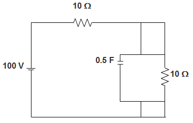
a) 1.5
b) 1.25
c) 2.5
d) 2.25
Answer: b
Explanation: We know that,
Time constant is given by Req.C
The equivalent resistance is given by,
Req = R || R
= \(\frac{R*R}{R+R}\)
= \(\frac{R}{2}\)
= 5 Ω
So, Time-constant = \(\frac{5X0.5}{2}\)
= 1.25.
15. In a dual slop integrating type digital voltmeter, the first integrating is carried out for 50 periods of the supply frequency of 50 Hz. If the reference voltage used is 10 V, the total conversion time for an input of 40 V is?
a) 3 s
b) 2 s
c) 4 s
d) 1 s
Answer: c
Explanation: In a dual slope integrating digital voltmeter,
\((\frac{t_1}{t_2})\) Vin = Vref
Where, t1 = first integration time = 50 × \(\frac{1}{50}\) = 1
But Vin = 40 V and Vref = 10 V
∴ t2 = \(\frac{V_{in} t_1}{V_{ref}}\) = 4 s.
Calculation of I(0+), di/dt(0+), d2I/dt2(0+) in Circuits Involving both Capacitor and Inductor
1. A coil of inductance 10 H, resistance 40 Ω is connected as shown in the figure. The switch S connected with point 1 for a very long time, is moved to point 2 at t=0. If, at t=0+, the voltage across the coil is 120 V, the value of the resistance R is __________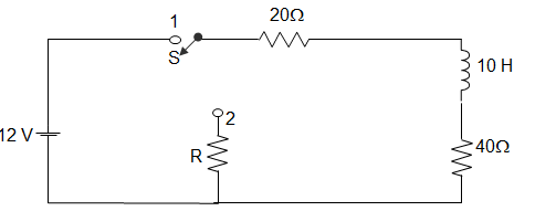
a) Zero
b) 20 Ω
c) 40 Ω
d) 60 Ω
Answer: a
Explanation: IL at 0– = \(\frac{120}{60}\) = 2A
120 = 2(R + 40 + 20)
∴ R = 0.
2. A coil of inductance 10 H, resistance 40 Ω is connected as shown in figure. The switch S connected with point 1 for a very long time, is moved to point 2 at t=0. For the value of R obtained, the time taken for 95 % of the stored energy dissipated is ________
a) 0.10 s
b) 0.15 s
c) 0.50 s
d) 1.0 s
Answer: c
Explanation: For source free circuit,
I (t) = Io\(e^{-\frac{R}{T} t}\)
∴ I (t) = 0.05 = 2 × \(e^{-\frac{60}{10} t}\)
Or, t = 0.61 ≈ 0.5 s.
3. In the circuit shown below steady state is obtained before the switch closes at t = 0. The switch is closed for 1.5 s and is then opened. At t = 1 s, V (t) will be?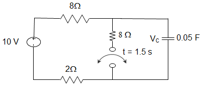
a) – 3.24 V
b) 1.97 V
c) 5.03 V
d) 13.24 V
Answer: c
Explanation: V (0–) = 10 V = V (0+)
For 0<t≤1.5 s, τ = 4 × 0.05 = 0.2 s
VOC = 5 V
V (t) = 5 + (10 – 5)\(e^{\frac{-t}{0.2}}\) = 5 + 5e-5t
V (1s) = 5.03 V.
4. The circuit shown below is at steady state before the switch closes at t=0. The switch is closed for 1.5 s and is then opened. At t = 2 s, V (t) will be?
a) 5.12 V
b) 6.43 V
c) 8.57 V
d) 9.88 V
Answer: c
Explanation: V (1.5s) = 5.002 V
For t > 1.5 s, τ = 8 × 0.05 = 0.4
V (t) = 10+ (5-10)\(e^{\frac{-(t-1.5)}{0.4}}\) = 10 – 5e-2.5(t-1.5)
For t≥1.5 s, V (2 s) = 8.57 V.
5. In the circuit given below, the voltage across capacitor when switch is closed at t = ∞ is ____________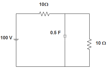
a) 50 V
b) 20 V
c) 30 V
d) 7.5 V
Answer: a
Explanation: From the figure, we can infer that,
Voltage across capacitor = voltage across 10 Ω resistance.
Now, voltage across the 10 Ω resistance = \(\frac{100}{10+10}\) X 10
= \(\frac{100}{20}\).10
= 50 V.
6. In the circuit given below, the current source is 1 A, voltage source is 5 V, R1 = R2 = R3 = 1 Ω, L1 = L2 = L3 = 1 H, C1 = C2 = 1 F. The current through R3 is _________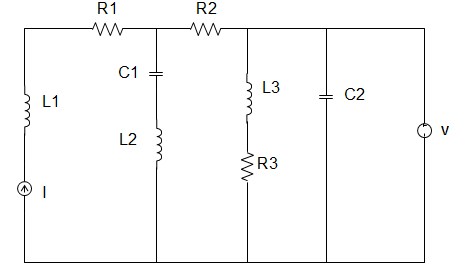
a) 1 A
b) 5 A
c) 6 A
d) 8 A
Answer: b
Explanation: At steady state, the circuit becomes,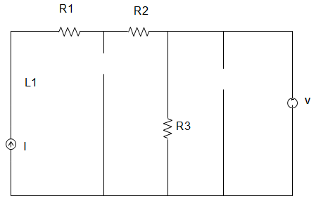
∴ The current through R3 = \(\frac{5}{1}\) = 5 A.
7. In the circuit given below, the capacitor is initially having a charge of 10 C. 1 second after the switch is closed, the current in the circuit is ________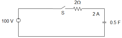
a) 14.7 A
b) 18.5 A
c) 40.0 A
d) 50.0 A
Answer: a
Explanation: Using KVL, 100 = R\(\frac{dq}{dt} + \frac{q}{C}\)
100 C = RC\(\frac{dq}{dt}\) + q
Or, \(\int_{q_o}^q \frac{dq}{100C-q} = \frac{1}{RC} \int_0^t \,dt\)
100C – q = (100C – qo)e-t/RC
I = \(\frac{dq}{dt} = \frac{(100C – q_o)}{RC} e^{-1/1}\)
∴ e-t/RC = 40e-1 = 14.7 A.
8. In the circuit given below, the current source is 1 A, voltage source is 5 V, R1 = R2 = R3 = 1 Ω, L1 = L2 = L3 = 1 H, C1 = C2 = 1 F. The current through the voltage source V is _________
a) 1 A
b) 3 A
c) 2 A
d) 4 A
Answer: d
Explanation: At steady state, the circuit becomes,
∴ The current through the voltage source V = 5 – 1 = 4 A.
9. In the circuit given below, the voltage across R by mesh analysis is _________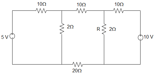
a) 1.59 V
b) 1 V
c) 2.54 V
d) 1.54 V
Answer: d
Explanation: In loop 1, by KVL, (10 + 2) I1 + (-2) I2 + 0I3 = 5
Or, 12 I1 – 2I2 = 5
In loop 2, -2I1 + (10+2+20+2) I2 + (-2) I3 = 0
Or, -2I1 + 34 I2 – 2I3 = 0
In loop 3, 0I1 + – 2I2 + (2+10) I3 = 10
Or, 0I1 – 2I2 + 12I3 = 10
Now, the voltage across R is VR = (I2 – I3) R
Now, I2 = \(\frac{360}{4800} = \frac{3}{40}\)
Now, I3 = \(\frac{4060}{4800} = \frac{203}{240}\) A
Therefore, VR = (I2 – I3) R = \(\Big[\frac{3}{40} – \frac{203}{240}\Big] 2\) = 1.54 V.
Application Of The Laplace Transform In Circuit Analysis MCQs
10. In a dual slop integrating type digital voltmeter, the first integrating is carried out for 10 periods of the supply frequency of 50 Hz. If the reference voltage used is 2 V, the total conversion time for an input of 1 V is _________
a) 0.01 s
b) 0.05 s
c) 0.1 s
d) 1 s
Answer: c
Explanation: In a dual slope integrating digital voltmeter,
\((\frac{t_1}{t_2})\) Vin = Vref
Where, t1 = first integration time = 10 × \(\frac{1}{50}\) = 0.25
But Vin = 1 V and Vref = 2 V
∴ t2 = \(\frac{V_{in} t_1}{V_{ref}}\) = 0.1 s.
11. A rectifier type AC voltmeter consists of a series resistance R, an ideal full-wave rectifier bridge and a PMMC instrument. The internal resistance and a full-scale deflection produced by a DC current are 100 Ω and 1 mA respectively. A voltage of 100 V (rms) is applied to the input terminals. The value of R required is _________
a) 63.56 Ω
b) 89.83 Ω
c) 89.83 kΩ
d) 141.3 kΩ
Answer: c
Explanation: VOAverage = 0.636 × \(\sqrt{2}\)Vrms = 0.8993 Vrms
The deflection with AC is 0.8993 times that with DC for the same value of voltage V
SAC = 0.8993 SDC
SDC of a rectifier type instrument is \(\frac{1}{I_{fs}}\) where Ifs is the current required to produce full scale deflection, Ifs = 1 mA; Rm = 100 Ω; SDC = 103 Ω/V
SAC = 0.8993 × 1000 = 899.3 Ω/V. Resistance of multiplier RS = SAC V – Rm – 2Rd, where Rd is the resistance of diode, for ideal diode Rd = 0
∴ RS = 899.3 × 100 – 100 = 89.83 kΩ.
12. A 1 μF capacitor is connected across a 50 V battery. The battery is kept closed for a long time. The circuit current and voltage across capacitor is __________
a) 0.5 A and 0 V
b) 0 A and 50 V
c) 20 A and 5 V
d) 0.05 A and 5 V
Answer: b
Explanation: We know that, when the capacitor is fully charged, it acts as an open circuit.
That is when the capacitor is fully charged.
So, the circuit current and voltage across capacitor are 0 A and 50 V respectively.
13. In the circuit given below, the switch is closed at t = 0. At t = 0+ the current through C is ___________
a) 2 A
b) 3 A
c) 4 A
d) 5 A
Answer: d
Explanation: We know that,
When the capacitor is fully charged, it acts as a short circuit.
The equivalent resistance Req = (10 + 10) Ω
= 20 Ω
Given voltage = 100 V
So, current through C = \(\frac{100}{20}\) A = 5 A.
14. A digital Multimeter reads 10 V when fed with a triangular wave, which is symmetric about the time-axis. If the input is same, the rms reading meter will read?
a) \(\frac{20}{\sqrt{3}}\)
b) –\(\frac{10}{\sqrt{3}}\)
c) –\(\frac{20}{\sqrt{3}}\)
d) \(\frac{10}{\sqrt{3}}\)
Answer: d
Explanation: For triangular wave Average value = \(\frac{V_m}{3}\), rms value = \(\frac{V_m}{\sqrt{3}}\)
∴ \(\frac{V_m}{3}\) = 10 V or, Vm = 30 V.
15. A resistance R is measured using the connection shown in the below figure.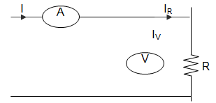
The current measured is 10 A on ranges 100A and the voltage measured is 125 V on 150 V range. The scales of the ammeter and voltmeter are uniform. The total number of scale divisions of the ammeter is 100 and that of the voltmeter is 150. The scale division can be distinguished. The constructional error of the ammeter is ± 0.3% and that of voltmeter±0.4%. The resistance of the ammeter is 0.25 Ω. The value of R is _________
a) 12.75 Ω
b) 12.0 Ω
c) 12.25 Ω
d) 12.5 Ω
Answer: c
Explanation: Percentage error in ammeter = ± \(\frac{1}{10×100}\) × 100 = ± 0.1%
Percentage error in voltmeter= ±\(\frac{1}{10 ×150}\) × 100 = ± 0.067%
So, δI = ± 0.3 ± 0.1 = ± 0.4%
δV = ± 0.4 ± 0.067 = ± 0.467%
R = \(\frac{V}{I}\)
So, error = ± δV ± δI = ± 0.867
Measured value of resistance = Rm = \(\frac{125}{10}\) = 12.5
∴ True value = Rm(1-\(\frac{R_a}{R_m}\)) = 12.25 Ω.
Advanced Problems on Application of Laplace Transform – 1
1. The resistance of a 230 V, 100 W lamp is ____________
a) 529 Ω
b) 2300 Ω
c) 5290 Ω
d) 23 Ω
Answer: a
Explanation: P = \(\frac{V^2}{R}\)
Or, R = \(\frac{V^2}{P}\)
Or, R = \(\frac{230 X 230}{100}\)
= 529 Ω.
2. A network has two branches in parallel. One branch contains impedance Za and the other branch has impedance Zb. If it is fed from an AC voltage V of frequency f, the current through Za depends, on which of the following?
a) V, Za, Zb
b) V, Za
c) Za, Zb
d) V, Za, f
Answer: d
Explanation: We know that, in parallel branches, the current through any branch depends only on V (voltage), Z (impedance) and f (frequency) only.
So, the current through Za depends on V, Za, and f.
3. Two coils having self-inductances of 1 mH and 2 mH are mutually coupled. The maximum possible mutual inductance is ___________
a) 1.414 mH
b) 2 mH
c) 1 mH
d) 5.5 mH
Answer: a
Explanation: We know that, maximum mutual inductance = L1L2
Given that, L1 = 1 mH and L2 = 2 mH
So, maximum mutual inductance = (1 X 2)0.5 = \(\sqrt{2}\)
= 1.414 mH.
4. A constant k band pass filter has a pass band from 100 to 400 Hz. The resonant frequency of series and shunt arms is ____________
a) 300 Hz
b) 250 Hz
c) 200 Hz
d) 150 Hz
Answer: c
Explanation: We know that,
Resonant frequency of arms in constant k band pass filter = [(fc1)(fc2)]0.5
Given that, fc1 = 100 Hz and fc2 = 400 Hz
So, Resonant frequency = \(\sqrt{100 X 400}\)
= 200 Hz.
5. An RLC series circuit has Q = 100 and ω0 = 20 rad/sec. The bandwidth is ____________
a) 0.2 rad/sec
b) 2 rad/sec
c) 20 rad/sec
d) 2000 rad/sec
Answer: a
Explanation: We know that,
Bandwidth = \(\frac{ω_0}{Q}\)
Given that, ω0 = 20 rad/sec and Q = 100
So, Bandwidth = \(\frac{20}{100}\)
= 0.2 rad/sec.
6. In an unloaded transformer, the flux limiting the primary is 10 mWb and secondary is 30 mWb. The coefficient of coupling is ____________
a) 1
b) 0.1
c) 0.33
d) 0.67
Answer: c
Explanation: Φ11 = (1 – k) Φ1
Or, φ11 = φ1 – φ2
Or, φ11 = 30 – 10 = 20 mWb
Now, 20 mWb = (1 – k) 30m
Or, 0.67 = 1 – k
Or, k = 0.33.
7. Poles and zeros of a driving point function of a network are simple and alternate on jω axis. The network consists of ___________
a) R and C
b) L and C
c) R and L
d) R, L and C
Answer: b
Explanation: In network having only L and C, poles and zeros of driving point function are simple and alternate on jω axis.
So, the network consists of L and C.
8. In a two terminals network the open circuit voltage measured at the given terminals is 110 V and short circuit currents at the same terminals 10 A. If a load of 50 Ω resistance is connected at the terminals, load current is ___________
a) 1.8 A
b) 1.25 A
c) 6 A
d) 6.25 A
Answer: a
Explanation: RTH = \(\frac{110}{10}\) = 11 Ω
So, I = \(\frac{110}{50+11}\) = 1.8 A.
9. A coil has resistance R and inductance L. At ω = ∞ the phase angle between voltage and current is _____________
a) 0°
b) 180°
c) 45°
d) 90°
Answer: d
Explanation: We know that,
When ω = ∞, XL = ωL = ∞.
Therefore, θ = tan-1 \(\frac{ωL}{R}\) = 90°.
10. An RLC series circuit has R = 7.07 Ω, L = .707 H and C = 7.07 μF. At Half power frequencies the circuit impedance is ___________
a) 7.07 Ω
b) 10 Ω
c) 14.14 Ω
d) 20 Ω
Answer: b
Explanation: We know that,
At half power frequency the circuit impedance is 2 times resistance
Given that, resistance = 7.07 Ω
So, circuit impedance = 2 X 7.07
= 14.14 Ω.
11. Two similar coils have self-inductance of 20 mH each. Coefficient of coupling is 0.4. The mutual inductance M is ______________
a) 2.5 mH
b) 8 mH
c) 7 mH
d) 1 mH
Answer: b
Explanation: We know that, the mutual inductance M is given by,
M = k\(\sqrt{L_1 L_2}\)
Given that, k = 0.4, L1 = 20 mH and L2 = 20 mH
So, M = 0.4\(\sqrt{20 X 20}\)1
= 8 mH.
12. For any given signal, average power in its 8 harmonic components as 50 mW each and fundamental component also has 50 mV power. Then, average power in the periodic signal is _______________
a) 750
b) 400
c) 100
d) 50
Answer: b
Explanation: We know that according to Parseval’s relation, average power is equal to the sum of the average powers in all of its harmonic components.
∴ Pavg = 50×8 = 400.
13. The Current Transformer supplies current to the current coil of a power factor meter, energy meter and, an ammeter. These are connected as?
a) All coils in parallel
b) All coils in series
c) Series-parallel connection with two in each arm
d) Series-parallel connection with one in each arm
Answer: b
Explanation: Since the CT supplies the current to the current coil, therefore the coils are connected in series so that the current remains the same. If they were connected in parallel then the voltages would have been same but the currents would not be same and thus efficiency would decrease.
14. A CRO probe has an impedance of 500 kΩ in parallel with a capacitance of 10 pF. The probe is used to measure the voltage between P and Q as shown in the figure. The measured voltage will be?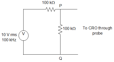
a) 3.53 V
b) 3.47 V
c) 5.54 V
d) 7.00 V
Answer: b
Explanation: XC = \(\frac{1}{jCω} = \frac{-j}{2 × 3.14 × 100 × 10^3 × 10 × 10^{-12}}\)
Applying KCL at node,
\(\frac{V_a-10}{100} + \frac{V_a}{100} + \frac{V_a}{500} + \frac{V_a}{-j159}\)
∴ Va = 4.37∠-15.95°.
15. M(t) = 2, 0≤t<4;
t2, t≥4;
The Laplace transform of W (t) is ___________
a) \(\frac{2}{s} – e^{-4s} \left(\frac{2}{s^3} – \frac{8}{s^2} – \frac{14}{s}\right)\)
b) \(\frac{2}{s} + e^{-4s} \left(\frac{2}{s^3} – \frac{8}{s^2} – \frac{14}{s}\right)\)
c) \(\frac{2}{s} – e^{-4s} \left(\frac{2}{s^3} + \frac{8}{s^2} + \frac{14}{s}\right)\)
d) \(\frac{2}{s} + e^{-4s} \left(\frac{2}{s^3} + \frac{8}{s^2} + \frac{14}{s}\right)\)
Answer: d
Explanation: M (t) = 2 + u (t) (t2 – 2)
L {2 + u (t) (t2 – 2)} = \(\frac{2}{s}\) + L {u (t) (t2 – 2)}
= \(\frac{2}{s} + e^{-4s}\) L {(t+4)2 -2}
= \(\frac{2}{s} + e^{-4s}\) L {t2 + 8t + 14}
= \(\frac{2}{s} + e^{-4s} \left(\frac{2}{s^3} + \frac{8}{s^2} + \frac{14}{s}\right)\).
Advanced Problems on Application of Laplace Transform – 2
1. A capacitor of 110 V, 50 Hz is needed for AC supply. The peak voltage of the capacitor should be ____________
a) 110 V
b) 460 V
c) 220 V
d) 230 V
Answer: c
Explanation: We know that,
Peak voltage rating = 2 (rms voltage rating).
Given that, rms voltage rating = 110 V
So, Peak voltage rating = 110 X 2 V
= 220 V.
2. Given I (t) = 10[1 + sin (- t)]. The RMS value of I(t) is ____________
a) 10
b) 5
c) \(\sqrt{150}\)
d) 105
Answer: c
Explanation: Given that, I (t) = 10[1 + sin (- t)]
Now, RMS value = \(\sqrt{10^2 + \frac{10^2}{\sqrt{2}}}\)
= \(\sqrt{100+50}\)
= \(\sqrt{150}\).
3. A two branch parallel circuit has a 50 Ω resistance and 10 H inductance in one branch and a 1 μF capacitor in the second branch. It is fed from 220 V ac supply, at resonance, the input impedance of the circuit is _____________
a) 447.2 Ω
b) 500 Ω
c) 235.48 Ω
d) 325.64 Ω
Answer: a
Explanation: We know that,
For a parallel resonance circuit impedance = \([\frac{L}{RC}]^{0.5}\)
Given, R = 50 Ω, L = 10 H and C = 1 μF
= \([\frac{10}{50*1}]^{0.5}\)
So, impedance = 447.2 Ω.
4. The impedance matrices of two, two-port network are given by [3 2; 2 3] and [15 5; 5 25]. The impedance matrix of the resulting two-port network when the two networks are connected in series is ____________
a) [3 5; 2 25]
b) [18 7; 7 28]
c) [15 2; 5 3]
d) Indeterminate
Answer: b
Explanation: Given that two impedance matrices are [3 2; 2 3] and [15 5; 5 25]. Here, the resulting impedance is the sum of the two given impedances.
So resulting impedance = [18 7; 7 28].
5. The electrical energy required to heat a bucket of water to a certain temperature is 10 kWh. If heat losses, are 10%, the energy input is ____________
a) 2.67 kWh
b) 3 kWh
c) 2.5 kWh
d) 3.5 kWh
Answer: a
Explanation: Given that, 10% of input is lost.
So, 0.90 Input = 10
Or, Input = \(\frac{10}{0.9}\) = 11.11 kWh.
6. The current rating of a cable depends on ___________
a) Length of the cable
b) Diameter of the cable
c) Both length and diameter of the cable
d) Neither length nor diameter of the cable
Answer: b
Explanation: We know that Current rating depends only on the area of cross-section. Since the area of cross section is a function of radius, which in turn is a function of diameter, so the current rating depends only on the Diameter of the cable.
7. In an AC circuit, the maximum and minimum values of power factor can be ___________
a) 2 and 0
b) 1 and 0
c) 0 and -1
d) 1 and -1
Answer: b
Explanation: We know that, power factor is maximum and equal to 1 for a purely resistive load. Power factor is minimum and equal to zero for a purely reactive load.
Hence, in an AC circuit, the maximum and minimum values of power factor are 1 and 0 respectively.
8. In the circuit given below, the series circuit shown in figure, for series resonance, the value of the coupling coefficient, K will be?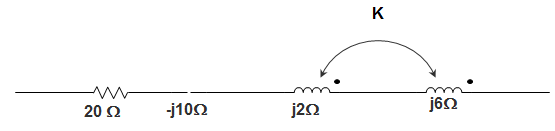
a) 0.25
b) 0.5
c) 0.1
d) 1
Answer: a
Explanation: Mutual inductance wm = ω k \(\sqrt{L_1 L_2}\)
Or, m = k.2.8 j2
= 4k.j
At resonance, Z = 20 – j10 + j2 + j6 + 2.4kj – 2j + 8kj = 0
Or, -2 = -8k
Or, k = \(\frac{1}{4}\) = 0.25.
9. In an RC series circuit R = 100 Ω and XC = 10 Ω. Which of the following is possible?
a) The current and voltage are in phase
b) The current leads the voltage by about 6°
c) The current leads the voltage by about 84°
d) The current lags the voltage by about 6°
Answer: b
Explanation: In RC circuit the current leads the voltage.
Or, θ = tan-1 \(\frac{10}{100}\)
This is nearly equal to 6°
Hence, the current lags the voltage by about 6°.
10. The impedance of an RC series circuit is 12 Ω at f = 50 Hz. At f = 200 Hz, the impedance will be?
a) More than 12
b) Less than 3
c) More than 3 Ω but less than 12 Ω
d) More than 12 Ω but less than 24 Ω
Answer: c
Explanation: We know that the impedance Z, is given by
Z = R2 + \(X_C^2\)
When f is made four times, XC becomes one-fourth but R remains the same.
So, the impedance is more than 3 Ω but less than 12 Ω.
11. A 3 phase balanced supply feeds a 3-phase unbalanced load. Power supplied to the load can be measured by ___________
a) 2 Wattmeter and 1 Wattmeter
b) 2 Wattmeter and 3 Wattmeter
c) 2 Wattmeter and 2 Wattmeter
d) Only 3 Wattmeter
Answer: b
Explanation: We know that, a minimum of 2 wattmeters is required to measure a 3-phase power. Also, power can be measured by using only one wattmeter in each phase. Hence, power supplied to the load can be measured by 2 Wattmeter and 3 Wattmeter methods.
12. A series RC circuit has R = 15 Ω and C = 1 μF. The current in the circuit is 5 sin 10t. The applied voltage is _____________
a) 218200 cos (10t – 89.99°)
b) 218200 sin (10t – 89.99°)
c) 218200 sin (10t)
d) 218200 cos (10t)
Answer: b
Explanation: Given that, R = 15Ω, XC = \(\frac{1}{ωC}\)
= \(\frac{10^6}{10 X 1}\) = 105 Ω
Now, θ = tan-1 \(\frac{X_C}{R}\) = 89.99°
We know that, impedance Z is given by,
Z = \(\sqrt{R^2 + X_C^2}\) = 102 kΩ.
Hence, V = 100000(2.182).sin(10 t – 89.99°)
Or, V = 218200 sin (10t – 89.99°).
13. A capacitor stores 0.15C at 5 V. Its capacitance is ____________
a) 0.75 F
b) 0.75 μF
c) 0.03 F
d) 0.03 μF
Answer: c
Explanation: We know that, Q = CV
Given, V = 5 V, Q = 0.15 C
Hence, 0.15 = C(5)
Or, C = 0.03 F.
14. For a transmission line, open circuit and short circuit impedances are 10 Ω and 20 Ω. Then characteristic impedance is ____________
a) 100 Ω
b) 50 Ω
c) 25 Ω
d) 200 Ω
Answer: d
Explanation: We know that, the characteristic impedance Z0 is given by,
Z0 = Zoc Zsc
Given that, open circuit impedance, Zoc = 10 Ω and short circuit impedance, Zsc = 20 Ω.
So, Z0 = (10.20) Ω
= 200 Ω.
15. A circuit excited by voltage V has a resistance R which is in series with an inductor and a capacitor connected in parallel. The voltage across the resistor at the resonant frequency is ___________
a) 0
b) \(\frac{V}{2}\)
c) \(\frac{V}{3}\)
d) V
Answer: a
Explanation: Dynamic resistance of the tank circuit, ZDY = \(\frac{L}{R_LC}\)
But given that RL = 0
So, ZDY = \(\frac{L}{0XC}\) = ∞
Therefore current through the circuit, I = \(\frac{V}{∞}\) = 0
∴ VD = 0.
Application of the Laplace Transform in Circuit Analysis MCQs ( Network Theory ) MCQs – Network Theory MCQs