Most Up To Date Transformers MCQs ( Electrical Machines ) MCQs – Electrical Machines MCQs

Latest Electrical Machines MCQs
By practicing these MCQs of Transformers MCQs ( Electrical Machines ) MCQs – Latest Competitive MCQs , an individual for exams performs better than before. This post comprising of objective questions and answers related to “Transformers MCQs ( Electrical Machines ) Mcqs “. As wise people believe “Perfect Practice make a Man Perfect”. It is therefore practice these mcqs of Electrical Machines to approach the success. Tab this page to check “Transformers MCQs ( Electrical Machines )” for the preparation of competitive mcqs, FPSC mcqs, PPSC mcqs, SPSC mcqs, KPPSC mcqs, AJKPSC mcqs, BPSC mcqs, NTS mcqs, PTS mcqs, OTS mcqs, Atomic Energy mcqs, Pak Army mcqs, Pak Navy mcqs, CTS mcqs, ETEA mcqs and others.
Electrical Machines MCQs – Transformers MCQs ( Electrical Machines ) MCQs
The most occurred mcqs of Transformers MCQs ( Electrical Machines ) in past papers. Past papers of Transformers MCQs ( Electrical Machines ) Mcqs. Past papers of Transformers MCQs ( Electrical Machines ) Mcqs . Mcqs are the necessary part of any competitive / job related exams. The Mcqs having specific numbers in any written test. It is therefore everyone have to learn / remember the related Transformers MCQs ( Electrical Machines ) Mcqs. The Important series of Transformers MCQs ( Electrical Machines ) Mcqs are given below:
Transformer Construction
1. The primary and secondary of a transformer are ________ coupled but _______ connected.
a) magnetically, not electrically
b) electrically, not magnetically
c) magnetically, also magnetically
d) electrically, also electrically
Answer: a
Explanation: Transformer is the machine which has physical spacing and has magnetic circuit to exchange the voltage.
2. We can employ transformers for a power range of _________
a) lower and higher values
b) lower values
c) higher values
d) medium values
Answer: a
Explanation: A transformer can be put in use upto a varying range of the power and it is usually available in readily in market.
3. A transformer has comparitively much higher efficiency than a similar induction machine due to _________
a) small air gaps
b) no moving parts
c) strong coupling
d) all of the mentioned
Answer: d
Explanation: Transformer does not has any moving components so losses are anyway reduced and also the coupling is very strong between two sides.
4. It was needed that to isolate dc noise coming from the transmitted signal, to attain the same which machine can be used without suffering significant loss?
a) transformer
b) dc machine
c) induction machine
d) stepper motor
Answer: a
Explanation: We should use transformer to achive the isolation of dc.
5. Which is the most widely used material in the core of the transformer?
a) cold rolled grain oriented sheet steel
b) cold rolled grain steel
c) soft iron
d) steel
Answer: a
Explanation: CRGO has magnetization in the rolling direction and low core losses and very high permeability than present materials.
6. The leakage flux is the flux in side the transformer which?
a) links either of the windings
b) links both of the windings
c) yoke of the core
d) windows of the core
Answer: a
Explanation: Leakage flux is meant to to be loss as it does not link two windings.
7. It is advised that staggering of the butt joints _________
a) reduces reluctance of the path
b) increases air gap
c) increases mechanical strength
d) all of the mentioned
Answer: c
Explanation: Staggering is done for the steel butt joints of the transformer to gain more mechanical strength as the continuous air gap reduces the same.
8. Consider two transformers X and Y having exact ratings, but have flux densities of 1.5T and 2T respectively. The weight of the transformer A per KVA will be _________
a) more than that of B
b) lesser than that of B
c) equal to that of B
d) can not be said from the given data
Answer: a
Explanation: Flux density = flux/Area.
Hence A has more area than B and so weight of A will be more than that of B.
9. Consider two transformers X and Y having identical ratings, but have flux densities of 1.5T and 2T respectively. The weight of the transformer B per KVA will be _________
a) more than that of A
b) lesser than that of A
c) equal to that of A
d) can not be said from the given data
Answer: b
Explanation: Flux density = flux/Area.
Hence A has more area than B and so weight of B will be less than that of A.
10. Transformers do not require any type of cooling as it well ventilated.
a) True
b) False
Answer: b
Explanation: It is wrong to say that transformers do not need any cooling. It does need various types of cooling like oil cooling, air cooled etc.
11. A coupling magnetic field inside a rotating machine or static machine like transformers must involve with _________
a) mechanical parts
b) electrical parts
c) both electrical and mechanical
d) either of the electrical or mechanical parts
Answer: a
Explanation: The coupling field should interact with both the electrical as well as mechanical parts in order to achieve electromechanical energy conversion.
12. A coupling magnetic field inside a rotating machine or static machine like transformers must involve with _________
I. electrical system to extract energy from electrical system.
II. mechanical system to extract energy from electrical system.
a) Only I is true
b) Only II is true
c) I and II are true
d) I and II are false
Answer: b
Explanation: The energy conversion which involves both electrical as well as mechanical systems must have mutual field.
13. I. Pulse transformers use soft ferrites.
II. The transformers used in the radio recievers use air core.
a) Only I is true
b) Only II is true
c) I and II are true
d) I and II are false
Answer: c
Explanation: Pulse transformers are used in isolation transformer and need high permeablity.
14. Stepping of the core is implemented in the core to _________
a) reduce conductor material and copper losses
b) reduce core loss
c) to provide mechanical strength
d) to reduce magnetizing current
Answer: a
Explanation: Stepping of the core is done so that the copper material reduces.
15. Core type transformers have, LV and HV windings are arranged such that _________
a) Half LV near the core and half HV outside LV on each limb
b) LV one one limb and HV on the other
c) Half LV outside the core and half HV inside LV on each limb
d) LV and HV windings are sandwiched
Answer: a
Explanation: Core windng has first of all both the windings on the same limb and HV is placed outside to have tappings to the transformer.
16. The shell type transformers have, LV and HV windings are arranged such that _________
a) Half LV near the core and half HV outside LV on each limb
b) LV one one limb and HV on the other
c) Half LV outside the core and half HV inside LV on each limb
d) LV and HV windings are sandwiched
Answer: d
Explanation: Shell type windng has mix of LV and HV winding sandwiched over each other.
Ideal Two Winding Transformer
1. Which of the following statements support the ideal transformer features?
I. Zero winding resistance
II. Zero leakage flux
III. Constant core losses
a) I, II
b) III
c) I, III
d) I, II, III
Answer: a
Explanation: Ideal transformer has zero or very small core or copper losses.
2. Which of the following statements support the ideal transformer features?
I. Zero winding resistance
II. Zero leakage flux
III. Negligible core losses
a) I, II, III
b) III
c) I, III
d) I
Answer: a
Explanation: All the statements support the ideal nature of a transformer.
3. Which of the following statements support the ideal transformer features?
I. Zero winding resistance
II. Constant permeability
III. Constant core losses
a) I, II
b) III
c) I, III
d) I
Answer: a
Explanation: Ideal transformer has constant permeability so that the magnetization of the core remains linear.
4. Which of the following statements support the ideal transformer features?
I. Zero winding resistance
II. Constant permeability
III. Constant core losses
Iv. Zero leakage reactance
a) I, II, III, IV
b) III, IV
c) I, III
d) I, IV
Answer: a
Explanation: An ideal transformer should be free from all types of losses and must have a linear magnetization of the core material.
5. Which of the following statements support the ideal transformer features?
I. Variable winding reactance
II. Constant permeability
III. Constant core losses
a) I, II
b) III
c) II, III
d) I
Answer: c
Explanation: There should not be any leakage reactance of the winding so that leakage flux is zero and complete coupling takes place.
6. The voltage induced at the end of primary terminals of a two winding transformer consisting of N turns is?
a) -N*dϕ/dt
b) N*dϕ/dt
c) -dϕ/dt
d) -N*dt/dϕ
Answer: a
Explanation: Emf is induced based on the electromagnetic induction principle for N turns winding.
7. Identify the phasor diagram for an ideal transformer at no load.
a) 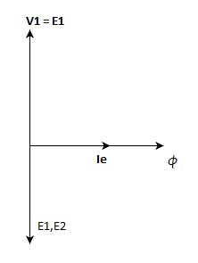
b) 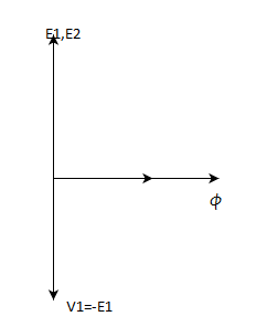
c) 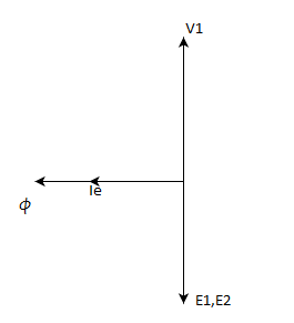
d) 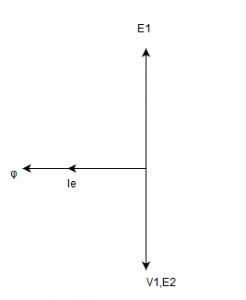
Answer: a
Explanation: In an ideal transformer, the induced emf lags the flux by 90degrees.
8. Consider a 2-winding transformer as below. If the switch is open then the emf induced across the load ‘Zl’ having transformation ratio of 2 is?
a) zero
b) V1
c) V1/2
d) 2*V1
Answer: a
Explanation: As the secondary switch is kept open, the voltage across load will be zero.
9. Consider a 2-winding transformer as below. If the switch is open then the emf induced across the secondary having transformation ratio of 2 is?
a) zero
b) V1
c) V1/2
d) 2*V1
Answer: d
Explanation: V2/V1 = 2
S, V2 = 2*V1.
10. Consider a 2-winding transformer as below. If the switch is kept open then the emf induced across the secondary having transformation ratio of ‘2’ is?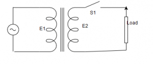
a) zero
b) 2E1
c) E/2
d) E1
Answer: a
Explanation: The induced emf lags the flux by 90degrees.
11. Which of the following statement is true?
I. Core flux in an ideal transformer remains constant.
II. Core flux is independent of the load current.
a) I
b) II
c) I,II
d) none of the mentioned
Answer: a
Explanation: Any changes in the secondary circuit of the transformer is reflected automatically in the primary winding so the net core flux remains constant.
12. If it is happened to place an inductive load to a two winding transformer, then the phasor diagram for such a loading will be?
a) 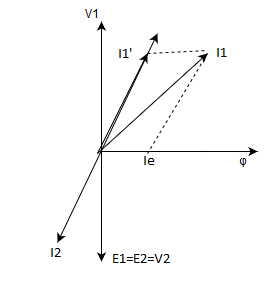
b) 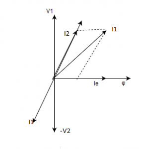
c)
d) 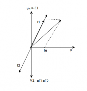
Answer: a
Explanation: I2 will lag behind the V2 by the angle θ.
13. Which of the following assumptions about the transformer supports the fact that the instantaneous power input and output of a transformer is equal?
I. Zero winding resistance
II. Constant permeability
III. Constant core losses
Iv. Zero leakage reactance
a) I,II,III,IV
b) III,IV
c) I,III
d) I,IV
Answer: c
Explanation: If the impedance overall is zero for a transformer, then the losses ocurring in a transformer will be zero. So the efficiency is 100%.
14. Which of the following statements are incorrect for an ideal transformer?
I. Voltages – inverse ratio
II. Current – direct ratio
III. Impedance – direct ratio squared
Iv. Power – remains same
a) I,II,III,IV
b) III,IV
c) I,II
d) I,IV
Answer: c
Explanation: Voltages are transformed in direct ratio of the turns ratio. and current as inverse turns ratio.
15. Which of the following statements are correct for an ideal transformer?
I. Voltages – Direct ratio
II. Current – Inverse ratio
III. Impedance – Direct ratio squared
Iv. Power – Remains same
a) I,II,III,IV
b) III,IV
c) I,III
d) I,IV
Answer: a
Explanation: All the matches are correct.
16. Which of the following statements are correct for an ideal transformer?
I. Voltages – inverse ratio
II. Current – direct ratio
III. Impedance – direct ratio squared
Iv. KVA – remains same
a) I,II,III,IV
b) III,IV
c) I,III
d) I,IV
Answer: b
Explanation: Voltages are transformed in direct ratio of the turns ratio. and current as inverse turns ratio in a 2-winding transformer.
Transformer Phasor Diagram
1. The output voltage seen at the CRO connected at the secondary terminals is square wave. Then the flux density used for energizing the primary is?
a) triangular
b) sinusoidal
c) saw tooth wave
d) square wave
Answer: a
Explanation: E = -N*dϕ/dt. Integration of square wave will be triangular in nature.
2. The non linear magnetization curve of a practical transformer will introduce _____________
a) heating
b) higher order harmonics
c) magnetostriction
d) all of the mentioned
Answer: d
Explanation: If the magnetization is non linear in nature then it will cause a saturation in the core and harmonics will be introduced to cause humming sounds.
3. Transformer action requires a ___________
a) constant magnetic flux
b) increasing magnetic flux
c) alternating magnetic flux
d) alternating electric flux
Answer: c
Explanation: As per the Faraday’s laws, the emf will be induced when flux is time varying as in transformer, there is no moving part.
4. If a transformer is fed from a 220V and dc supply rather than a 1-phase ac supply, then the transformer will ___________
a) burn its windings
b) operate normal
c) will not operate
d) will give very small leakage flux
Answer: a
Explanation: Dc is nothing but ac at zero frequency. So the reactance offered will be zero at dc and the current will be limited only by the small resistance of the winding which will produce very high amount of current to flow through the windings, so burning them up.
5. In an ideal transformer, the impedance can be transformed from one side to the other ___________
a) in direct proportion to square of turns-ratio
b) in direct proportion to turns-ratio
c) in inverse proportion to square turns-ratio
d) in inverse proportion to turns-ratio
Answer: a
Explanation: Impedance is transformed in square of the turns-ratio.
6. A transformer has sometimes more than two ratings depending upon the use of ___________
a) the cooling application
b) type of windings
c) type of core
d) type of insulation to be given
Answer: a
Explanation: Yes, with different types of the cooling methods, the losses can be varied and so the current and the voltages.
7. Considering a transformer at no load is excited at rated voltage. A small recognizable gap is made in the yoke of the limbs. With this altercation, the transformer core flux ___________
a) will decrease and magnetizing current will increase
b) will remain constant and magnetizing current will increase
c) as well as magnetizing current will increase
d) as well as magnetizing current both will decrease
Answer: b
Explanation: The reluctance of the path increases here after making the cut. so the magnetizing current will increase but the core flux will be same as it depends on the applied voltage not the reluctance.
8. In an oil filled transformer, the application of oil is for ___________
a) cooling
b) insulation
c) both cooling and insulation
d) preventing the accumulation of dust
Answer: c
Explanation: Oil can be used not only for cooling but also for insulation from the metallic parts.
9. We laminate transformer core to reduce ___________
a) eddy current loss
b) hysteresis loss
c) both eddy current and hysteresis loss
d) ohmic loss
Answer: a
Explanation: Laminations provide larger area so that the current path increases and current reduces.
10. Which of the following two are matched correctly?
I. Core flux – Depends on applied voltage
II. Leakage flux – Depends on winding current
a) I
b) II
c) I, II
d) none of the mentioned
Answer: a
Explanation: Both the statements are correct, as the leakage flux depends on the current flowing in the respective winding and the core flux depends on the voltage.
11. In case of a power transformer, the no load current in terms of rated correct is?
a) 10-20%
b) 2-6%
c) 15-20%
d) 30-50%
Answer: b
Explanation: The air gap is very less in the transformer, so the magnetizing current needed is around 2-6% only.
12. Energizing the transformer primary from a triangular wave voltage source makes the output voltage as __________
a) zero
b) a sine wave
c) a triangular wave
d) a pulsed wave
Answer: c
Explanation: Output will follow the shape of input wave. As the primary input is triangular in shape, its secondary will also be same.
13. In a single phase transformer, the no-load current lags the applied voltage by __________
a) 90°
b) about 75°
c) 0
d) about 110°
Answer: b
Explanation: Check the phasor diagram.
14. A 400/200V transformer has total resistance of 0.04 p.u on its L.V side. This resistance when referred to H.V side would be?
a) 0.04
b) 0.02
c) 0.01
d) 0.08
Answer: a
Explanation: The per unit value does not change from the winding side of a transformer.
15. Energising the transformer primary from a triangular wave flux makes the output voltage as __________
a) square wave shifted by 90°
b) a sine wave
c) a triangular wave
d) a square wave
Answer: d
Explanation: E = -N*dϕ/dt.
Differentiation of triangular wave results in square wave.
Equivalent Circuit of Transformer
1. In a transformer if the frequency of the supply is varied then the magnetizing current in the core also varies.
a) True
b) False
Answer: b
Explanation: The magnetizing current does not depend on the frequency of the supply fed to it.
2. CRGO Laminations in a transformer are used to minimize __________
a) eddy current loss
b) hysteresis loss
c) both eddy current and hysteresis loss
d) ohmic loss
Answer: c
Explanation: CRGO steel is rolled grain type domains which not only help for faster reversals but also the reduction of eddy current losses.
3. A single phase transformer has emf per turn having 2310/220 V, 50Hz transformer as 13 V. Then the estimated primary turns will be?
a) 189 turns
b) 179 turns
c) 176 turns
d) 190 turns
Answer: a
Explanation: N2 = Total secondary voltage/Emf per turn
= 220/13 = 16.92 = 17(approx)
For N2 = 17, N1 = 178.5. But it is not an integer, so this approximation is wrong.
If N2 = 18, N1=189 turns.
4. A single phase transformer has emf per turn having 2310/220 V, 50Hz transformer as 13 V. The core area is(in square cm)?
a) 393
b) 277.8
c) 358.92
d) 450.03
Answer: a
Explanation: Emf per turn = 1.44*f*flux density * Area*N2
Area = 220/(18*1.44*50*1.4) = 393 sq.cm.
5. If a transformer is fed from a dc rather than a 1-phase ac supply, then the transformer will __________
a) burn its windings
b) operate normal
c) will not operate
d) will give very small leakage flux
Answer: a
Explanation: Dc is nothing but ac at zero frequency. So the reactance will be zero and the current will be limited solely by the small resistance of the winding which will produce very high amount of current to flow through the windings, so burning them up.
6. For a single phase transformer operating at normal operating conditions has useful flux of 1 Wb. If the machine is loaded at 0.8 p.f., then its mutual flux __________
a) may decrease to 0.98 Wb
b) remains constant
c) may increase 1.02 Wb
d) may decrease to 0.8 Wb
Answer: a
Explanation: The mutual flux will decrease by a very small amount.
7. The flux involved in the emf equation of a transformer has __________
a) rms value
b) average value
c) total value
d) maximum value
Answer: d
Explanation: The flux is always taken at its peak in the practical calculation cases.
8. If the frequency at the primary supply is varied gradually, then the secondary terminal voltage will __________
a) not change
b) vary directly
c) will vary oppositely
d) will vary inverse of frequency
Answer: a
Explanation: The changes in the frequency is not reflected due to the flux density variation correspondingly.
9. There are two identical transformers A and B such that flux density applied to B is doubled. Then magnetizing current of B is?
a) larger than A
b) double of A
c) half of A
d) same as that of A.
Answer: a
Explanation: When we double the flux density, as per the magnetization curve of the core, the magnetizing current is much larger than double of the machine A.
10. A 20KVA, 2200/220 V, 50 Hz single phase transformer has the below parameters:
HV : r = 2.4 Ω, X = 6 Ω
LV: r = 0.03 Ω, X = 0.07 Ω
The primary reactance referred to secondary is?
a) 0.024 Ω
b) 0.06 Ω
c) 3 Ω
d) 7 Ω
Answer: b
Explanation: Primary reactance referred to secondary = x1*(N2/N1)^2 = 6*(220/2200)^2
= 0.06 Ω.
11. A 20KVA, 2200/220 V, 50 Hz single phase transformer has the below parameters:
HV : r = 2.4 Ω, X = 6 Ω, Primary
LV: r = 0.03 Ω, X = 0.07 Ω, Secondary
The secondary reactance referred to primary is?
a) 0.024 Ω
b) 0.06 Ω
c) 3 Ω
d) 7 Ω
Answer: d
Explanation: Secondary reactance referred to primary = x2*(N1/N2)^2 = 0.07*(2200/220)^2 = 7.0 Ω
12. A 20KVA, 2200/220 V, 50 Hz single phase transformer has the below parameters:
HV : r = 2.4 Ω, X = 6 Ω
LV: r = 0.03 Ω, X = 0.07 Ω
The primary resistance referred to secondary is?
a) 0.024 Ω
b) 0.06 Ω
c) 3 Ω
d) 7 Ω
Answer: a
Explanation: Primary resistance referred to secondary = r1*(N2/N1)^2 = 2.4*(220/2200)^2
= 0.024 Ω.
13. A 20KVA, 2200/220 V, 50 Hz single phase transformer has the below parameters:
HV : r = 2.4 Ω, X = 6 Ω
LV: r = 0.03 Ω, X = 0.07 Ω
The secondary resistance referred to primary is?
a) 0.024 Ω
b) 0.06 Ω
c) 3 Ω
d) 7 Ω
Answer: c
Explanation: Secondary resistance referred to primary = r2*(N1/N2)^2 = 0.03*(2200/220)^2 = 3.0 Ω.
14. In a transformer ______ decreases with increase of the leakage flux.
a) secondary terminal voltage
b) secondary induced voltage
c) primary induced voltage
d) all of the mentioned
Answer: a
Explanation: The leakage is modelled as the reactance which incurrs as a loss to the terminal voltage not the induced voltage.
15. The components needed to draw the phasor diagram of the transformer is?
A. load current
B. Equivalent circuit parameters
C. Load power factor
a) A, B, C
b) B
c) B, C
d) A, B
Answer: a
Explanation: All the mentioned quantities are must to draw the phasor diagram of a transformer.
Open Circuit and Short Circuit Test
1. Power required during the open circuit and short circuit test is?
a) losses incurring in the transformer
b) executing the power requirements by measuring instruments
c) power for the core losses only
d) all of the mentioned
Answer: a
Explanation: The power measured while conducting the tests is the winding losses and the core losses.
2. The open circuit test results in finding which of the following parameters?
I. core losses
II. shunt branch parameters
III. turns ratio of transformer
a) I, II, III
b) I, II
c) II, III
d) I, III
Answer: a
Explanation: OC test gives the shunt branch parameters as well as the turns ratio by connecting a voltmeter at open circuited secondary terminals.
3. The open circuit test results in finding which of the following parameters?
I. core losses
II. shunt branch parameters
III. series parameters
a) I, II, III
b) I, II
c) II, III
d) I, III
Answer: b
Explanation: Series parameters are obtained by short circuit test results.
4. Which of the following informations are obtained from short-circuit test?
I. Ohmic losses at rated current
II. Equivalent resistance and leakage reactance
III. Core losses
IV. Voltage regulation
a) I, II, IV
b) II, III
c) I, II, IV
d) II, III, IV
Answer: a
Explanation: Core losses are found from OC test.
5. Which of the below estimations require results of both open circuit test and short circuit test?
a) Efficiency
b) Equivalent impedance of one side of the winding
c) Voltage regulation for exact circuit
d) All of the mentioned
Answer: a
Explanation: All the estimations asked will need results of both the tests.
6. To conduct the open circuit test, test is conducted on the _____________
a) l.v. side
b) h.v. side
c) primary
d) secondary
Answer: a
Explanation: OC test is performed on the l.v. side of the transformer because the l.v. winding will have lower stress on the insulation and no damage will occur.
7. To conduct the short circuit test, test is conducted on the ___________
a) l.v. side
b) h.v. side
c) primary
d) secondary
Answer: b
Explanation: To circulate the rated current in the winding, we should opt for lower value of the current so that winding will not damage.
8. A single phase transformer of 2200/220 V having rated l.v. current of 150 A has to undergo open circuit test on h.v. side. Which of the below instruments range should be used?
a) 6A, 200V
b) 150A, 22V
c) 60A, 220V
d) 6A, 20V
Answer: a
Explanation: Open circuit test is conducted on l.v. side, so the measuring instruments will be on the h.v. side.
So the current in the h.v. side will be around 3-6% of the rated.
9. A single phase transformer of 2000/200 V having rated l.v. current of 100 A has to undergo short circuit test on l.v. side. Which of the below instruments range should be used?
a) 200V,10A
b) 20V, 10A
c) 300V,100A
d) 200V,50A
Answer: a
Explanation: Short circuit test is conducted on h.v. side, so the measuring instruments will be on the l.v. side.
Rated current on the h.v. will be 10A and voltage will be around 5-12% to account for winding losses.
10. A single phase transformer of 2200/220 V having rated l.v. current of 150 A has to undergo open circuit test on h.v side. The instruments used are voltmeter of 200V and ammeter of 1A. Then the results ___________
a) will be wrong
b) will be accurate
c) of ammeter will burn
d) none of the mentioned
Answer: c
Explanation: The current in the h.v. winding will be around 10 A but the ammeter is of 1 A rating. So, it will burn off.
11. Which of the following conditions have to ensured for a short-circuit test?
A. L.v. is short circuited
B. It helps in calculation of voltage regulation
C. It is performed at rated voltage
a) A, B
b) A, B, C
c) B, C
d) A, C
Answer: a
Explanation: For conducting short circuit test, l.v. winding is short circuited and it is not performed at rated voltage.
12. Which of the following conditions have to ensured for a short-circuit test?
A. h.v. winding is short-circuited
B. It helps in calculation of voltage regulation
C. It is performed at rated voltage
D. l.v. winding is short-circuited
a) B, D
b) A, B, C
c) B, C, D
d) A, C
Answer: a
Explanation: For conducting short circuit test, l.v. winding is short circuited and it is not performed at rated voltage.
13. Transformers with high leakage impedance is used in ___________
a) arc welding
b) power distribution
c) power generating terminals
d) none of the mentioned
Answer: a
Explanation: The feature of the high impedance is extracted in the arc welding applications.
14. Which of the following conditions have to ensured for a open-circuit test?
A. Performed on L.V side
B. Leakage impedance can be obtained
C. It is performed at rated voltage
D. It gives magnetizing impedance
a) B, D
b) A, B, C
c) B, C, D
d) A, C, D
Answer: d
Explanation: Leakage impedance is not found from open-circuit test.
15. Which of the following conditions have to ensured for a open-circuit test?
A. Performed on L.V side
B. Leakage impedance can be obtained
C. It is performed at 10-12% of rated voltage
D. It gives magnetizing impedance
a) B, D
b) A, B, C
c) B, C, D
d) A, D
Answer: a
Explanation: Leakage impedance is not found from open-circuit test. And it is performed on the rated voltage to account for core losses.
16. Which of the following informations are not obtained from short-circuit test?
I. Ohmic losses at rated current
II. Equivalent resistance and leakage reactance
III. Core losses
IV. Voltage regulation
a) I, II
b) II, III
c) I, II, IV
d) II, III
Answer: d
Explanation: Core losses are found from OC test and the voltage regulation is not obtained from one single test here.
Voltage Regulation of Transformer
1. A 10 kVA, 400/200 V, 1-phase transformer with 2% resistance and 2% leakage reactance. It draws steady short circuit current at which angle?
a) 45°
b) 75°
c) 135°
d) 0°
Answer: a
Explanation: The power factor angle will be atan(x/r) = 45°.
2. While conducting open circuit test and short circuit test on a transformer, status of low-voltage and high-voltage windings will be such that in ____________
a) OC test – h.v. open, SC test-l.v. short-circuited
b) OC test – l.v. open, SC test-h.v. short-circuited
c) OC test – l.v. open, SC test-l.v. short-circuited
d) OC test – h.v. open, SC test-h.v. short-circuited
Answer: a
Explanation: In conducting short circuit test, l.v. winding is short circuited. In OC test h.v. is open circuited.
3. While conducting testing on the single phase transformer, one of the student tries to measure the resistance by putting an ammeter across one terminal of primary and other to secondary, the reading obtained will be ___________
a) infinite
b) zero
c) finite
d) negative finite
Answer: a
Explanation: As the primary and secondary are physically isolated, the impedance will be infinite for not electrically connected circuit.
4. If the per unit leakage impedance for the primary of a transformer is ‘x’ on the given rated base value. If the voltage and volt-amperes are doubled, then the changed per unit impedance will be ___________
a) 0.5x
b) 2x
c) 4x
d) x
Answer: a
Explanation: pu(new base) = (x)*(MVA(new)/MVA(old))*(kV(old)/kV(new))^2
= x*2*(1/4)
= 0.5x.
5. If the per unit leakage impedance for the primary of a transformer is ‘x’ on the given rated base value. If the voltage and volt-amperes are halved, then the changed per unit impedance will be ___________
a) 0.5x
b) 2x
c) 4x
d) x
Answer: b
Explanation: pu(new base) = (x)*(MVA(new)/MVA(old))*(kV(old)/kV(new))^2
= x*0.5*(4/)
= 2x.
6. The voltage regulation for transformer is given by ___________
a) (E2-V2)/E2
b) (E2-V2)/V2
c) (V2-E2)/E2
d) (V2-E2)/V2
Answer: a
Explanation: Voltage regulation is the change in secondary voltage with secondary rated voltage.
7. While estimating voltage regulation of a transformer, keeping ___________
a) primary voltage constant
b) secondary voltage constant
c) voltage changes constant at primary
d) all of the mentioned
Answer: a
Explanation: V.R. is calculated keeping the primary constant because then the core flux will change and the change of secondary voltage can not be fixed.
8. Identify the phasor diagram for the negative voltage regulation from the below diagrams.
a) 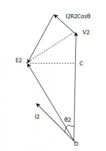
b) 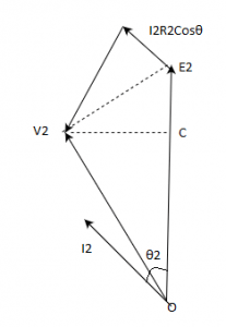
c) 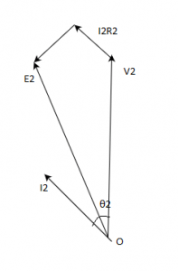
d) 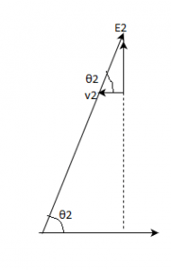
Answer: a
Explanation: Negative V.R. is achieved at leading power factor.
9. Identify the phasor diagram for the zero voltage regulation from the below diagrams.
a)
b) 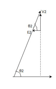
c)
d) 
Answer: a
Explanation: When E2=V2, then V.R. will be zero.
10. Identify the phasor diagram for the maximum voltage regulation from the below diagrams.
a)
b)
c)
d)
Answer: a
Explanation: Maximum voltage regulation occurs when load power factor angle and leakage impedance angle are equal.
11. The transformer phasor diagram under the short circuit can be identified by?
a) 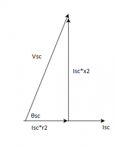
b)
c)
d)
Answer: a
Explanation: For the short-circuit condition of a transformer, voltage across the secondary will be voltage drop across winding only.
12. With the reference of the diagram below, Choose the most appropriate.
A: 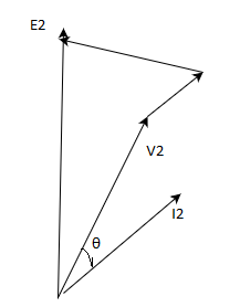
B:
a) A-lagging pf, B-leading pf
b) B-lagging pf, A-leading pf
c) A-lagging pf, B-lagging pf
d) A-leading pf, B-leading pf
Answer: a
Explanation: Maximum voltage regulation occurs at lagging pf while zero or minimum V.R. occurs at leading pf.
13. A 200/400 V single phase transformer has leakage impedance z= r+jx. Then we can expect zero voltage regulation at power factor of ___________
a) x/r leading
b) x/r lagging
c) r/x leading
d) r/x lagging
Answer: a
Explanation: ZVR occurs at the leading pf of load at x/r.
14. A 200/400 V single phase transformer has leakage impedance z= r+jx. Then we can expect magnitude of load pf of ____ at zero voltage regulation.
a) cosθ = x/z
b) cosθ = r/z
c) cosθ = x/r
d) cosθ = r/x
Answer: a
Explanation: Cosθ = x/z for the transformer at zero V.R.
15. If the pu impedance of a single phase transformer is 0.01+j0.05, then its regulation at p.f. of 0.8 lagging will be?
a) 3.8%
b) 2.2%
c) -3.8%
d) -2.2%
Answer: a
Explanation: V.R. = (r(pu)*cosθ+x(pu)*sinθ)*100 % = (0.01*0.8 + 0.05*0.6)*100 = 3.8%.
16. If the pu impedance of a single phase transformer is 0.01+j0.05, then its regulation at p.f. of 0.8 leading will be?
a) 3.8%
b) 2.2%
c) -3.8%
d) -2.2%
Answer: d
Explanation: V.R. = (r(pu)*cosθ-x(pu)*sinθ)*100 % = (0.01*0.8 – 0.05*0.6)*100 = -2.2%.
Transformer Losses and Efficiency
1. Which of the statements made here are correct regarding the transformer?
I. Maximum voltage regulation occurs at the leading p.f.
II. Maximum voltage regulation occurs when load p.f. angle and
impedance angle of the leakage impedance are same.
III. V.R. at zero p.f. is always zero.
IV. V.R. of a transformer may be negative at leading p.f.
a) I, III
b) II, IV
c) 1, III
d) I, IV, III
Answer: b
Explanation: V.R. is always negative at leading p.f. and the load p.f. angle and impedance angle of the leakage impedance should be same for maximum V.R.
2. Which of the statements made here are correct regarding the transformer?
I. Maximum voltage regulation occurs at the leading p.f.
II. Maximum voltage regulation occurs when load p.f. angle and
impedance angle of the leakage impedance are same.
III. V.R. at zero p.f. is always zero.
IV. V.R. of a transformer may be negative at leading p.f.
a) I, II, III
b) II, IV
c) 1, III
d) I, IV, III
Answer: a
Explanation: V.R. is always negative at leading p.f. and the load p.f. angle.
3. Which of the statements made here are incorrect regarding the transformer?
I. Maximum voltage regulation occurs at the leading p.f.
II. Maximum voltage regulation occurs when load p.f. angle and
impedance angle of the leakage impedance are same.
III. V.R. at zero p.f. is always zero.
IV. V.R. of a transformer may be negative at leading p.f.
a) I,III
b) II,IV
c) 1,III
d) I,IV,III
Answer: a
Explanation: V.R. is always negative at leading p.f. and the load p.f. angle and impedance angle of the leakage impedance should be same for maximum V.R.
4. Which of the statements made here are incorrect regarding the transformer?
I. Maximum voltage regulation occurs at the leading p.f.
II. Maximum voltage regulation occurs when load p.f. angle and
impedance angle of the leakage impedance are same.
III. V.R. at zero p.f. is always zero.
IV. V.R. of a transformer may be negative at leading p.f.
a) I,II,III
b) IV
c) 1,III
d) I,IV,III
Answer: b
Explanation: V.R. is always negative at leading p.f. and the load p.f. angle.
5. Which of the following mentioned losses occur in a transformer?
a) Hysteresis losses; Eddy current losses; Dielectric losses; Stray load losses
b) Hysteresis losses; Eddy current losses;
c) Dielectric losses; Stray load losses
d) Hysteresis losses; Eddy current losses; Stray load losses
Answer: a
Explanation: Hysteresis losses-due to magnetic material; Eddy current losses-on the core area; Dielectric losses- due to insulation material; Stray load losses- due to leakage through the parts of the transformer.
6. Mutual flux ______ at the lagging loading and it _____ at the leading power factor.
a) decreases, increases
b) increases, increases
c) decreases, decreases
d) increases, decreases
Answer: a
Explanation: The mutual flux falls when the transformer is working at lagging p.f. and it increases at leading p.f.
7. It is possible to attain maximum efficiency in a transformer when the ______
a) core losses are equal to rated full load copper losses
b) core losses are more than rated full load copper losses
c) core losses and full load copper losses are constant
d) copper loss also becomes constant
Answer: a
Explanation: Maximum efficiency is achieved at the condition when fixed core losses and copper losses at rated condition are equal.
8. The efficiency of a 20 KVA, 2000/200 V, single phase transformer at unity pf is 98%. The total losses at this condition is?
a) 408W
b) 4.08kW
c) 204W
d) 2.04kW
Answer: a
Explanation: Efficiency = 1-(losses/input) = 1-(losses/output+losses)
0.98 = 1-(Losses/20000+losses)
Losses = 408 W.
9. The efficiency of a 20 KVA, 2000/200 V, single phase transformer at unity pf is 98%. The given total losses at full load is 200 W. The pu resistance is?
a) 0.01
b) 0.1
c) 1.0
d) 0.0196
Answer: a
Explanation: pu resistance = Ohmic losses/KVA = 200/20000 = 0.01 pu.
10. The load current at which maximum efficiency occurs is independent of the load power factor.
a) True
b) False
Answer: b
Explanation: Because Core losses and the effective resistance of the secondary are almost unaffected by load p.f.
11. The full load voltage drop in a 1-phase transformer is 2% and 4% respectively due to resistance and leakage reactance. Then the voltage drop is maximum at __________
a) 0.45 lagging
b) 0.45 leading
c) 0.9 lagging
d) 0.9 leading
Answer: a
Explanation: Z = 4.47; cosθ = percentage r/percentage z = 2/(4.47) = 0.45.
12. The full load voltage drop in a 1-phase transformer is 2% and 4% respectively due to resistance and leakage reactance. Then the voltage drop is zero at __________
a) 0.45 lagging
b) 0.45 leading
c) 0.9 lagging
d) 0.9 leading
Answer: c
Explanation: Z = 4.47; cosθ = percentage x/percentage z = 4/4.47 = 0.89.
13. Core losses of a transformer as a function of frequency is best approximated by which of the below characteristics?
a) 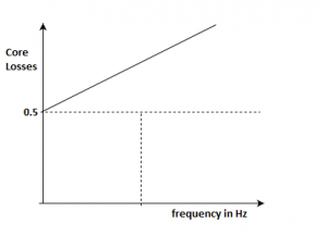
b)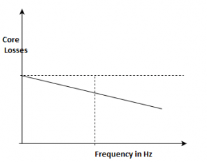
c)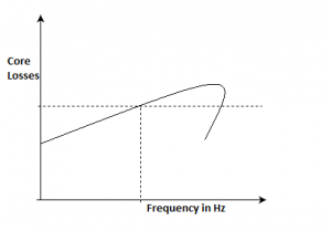
d)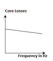
Answer: a
Explanation: We can represent the core losses per cycle eq. as Pc/f = A+B*f, where A and B are constants.
14. From the above graph of the core losses per cycle is, the hysteresis losses per phase for a transformer at a operating frequency of 40 Hz is?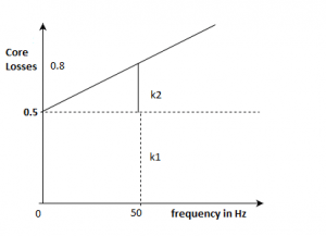
a) 20W
b) 30W
c) 80W
d) 32W
Answer: a
Explanation: Ph = k1*f = 0.5*40 = 20W.
15. From the above graph of the core losses per cycle is, the eddy losses per phase for a transformer at a operating frequency of 40 Hz is?
a) 15 W
b) 20W
c) 35W
d) 32W
Answer: a
Explanation: Pe = k2*f2;
Using the slope of the line, (k2)*50 = 0.8 – 0.5 = 0.3
(k2) = 0.006
Pe = 50*50*0.006 = 15 W.
16. The efficiency of a transformer can be calculated accurately from ___________
a) Open circuit test, Short circuit test
b) Open circuit test, Short circuit test, Sumpner’s test
c) Sumpner’s test
d) load test
Answer: a
Explanation: OC and SC tests together can help to estimate the most correct value of the efficiency for the given transformer.
Parallel Operation of Single Phase Transformers
1. A 2000/1000/500 three winding transformer is to be used as auto transformer with supply of 3000 V. Two loads of 1050 kVA at 3500V, and other one at 180 kVA at 1000V. The circuit representing the mentioned application is?
a) 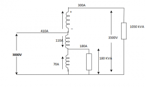
b) 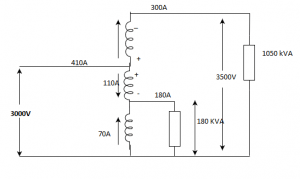
c) 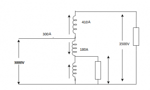
d)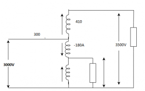
Answer: a
Explanation: Current due to load of 1050 kVA = 1050*1000/3500 = 300A
Current due to 180 kVA = 180*1000/1000 = 180A.
2. Transformer operating in parallel will share a common load in the best possible manner if ____________
a) leakage impedances are proportional to their kVA rating
b) pu leakage impedances are equal
c) leakage impedances are equal
d) any of the mentioned
Answer: b
Explanation: For same pu leakage impedance, parallel operation of transformers become feasible.
3. A 2000/1000/500 three winding transformer is to be used as auto transformer with supply of 3000 V. Two loads of 1050 kVA at 3500V and other one at 180 kVA at 1000V. The total kVA supplied will be?
a) 1230 kVA
b) 1440 kVA
c) 1680 kVA
d) 1150 kVA
Answer: a
Explanation: Total kVA = 1050+180 = 1230 kVA.
4. Which if the conditions is must be fulfilled for satisfactory parallel operation of transformers?
a) Same voltage ratio
b) Leakage impedances should be inversely proportional to kVA of the transformer
c) Same pu impedance
d) Correct polarity
Answer: d
Explanation: out of all, polarity must be correct for the connected transformers.
5. Which of the following is the correct matching made for the harmonics and the associated harmonic component?
A. Positive sequence components – 5th harmonic component
B. Negative sequence components – 7th harmonic component
C. Zero sequence components – 3rd harmonic component
a) A, B, C
b) C
c) A, B
d) B, C
Answer: b
Explanation: 3m-1 phases are displaced 120° in opposite and (3m+1) in the same direction as the fundamental. Here ‘m’ is even integer. So 5th harmonic is in negative sequence and 7th harmonic component in positive sequence.
6. Two single phase transformers A and B are operating in parallel having same impedance. But the x/r ratio of them are not equal. Then total kVA output of the output will be ___________
a) less than sum of kVA of A and B
b) more than sum of kVA of A and B
c) equal to sum of kVA of A and B
d) any of the mentioned
Answer: a
Explanation: As the leakage reactances are not same for both the transformers, then Ia < I2 and Ib < I/2.
So the kVA will also be less than sum of individual A and B.
7. Two single phase transformers A and B are operating in parallel having same impedance. But the x/r ratio of them are not equal and xa > xb. Then?
a) A has poorer pf than B
b) B has poorer pf than B
c) lesser power factor angle
d) both operate at same power factor
Answer: a
Explanation: As xa > xb, leakage impedance angle of A will be more than that of B, so lesser power factor.
8. Two single phase transformers A and B are operating in parallel having different impedance and identical x/r ratio. Then?
a) A has poorer pf than B
b) B has poorer pf than B
c) lesser power factor angle
d) both operate at same power factor
Answer: d
Explanation: As the x/r is same, this supports that they should have same leakage impedance angles.
9. Two single phase transformers A and B are operating in parallel having different impedance and identical x/r ratio. Also impedance of A is more than that of B, then A ___________
a) shares lesser kVA
b) share more kVA
c) equal kVA as of B
d) total kVA
Answer: a
Explanation: Given that, za is more than zb, so Ia will be lesser than Ib, With Ea = Eb, kVA(A) shared by A will more than kVA(B).
10. Two single phase transformers A and B are operating in parallel having different impedance and identical x/r ratio. Also impedance of A is more than that of B, then?
a) Za/Zb = Sb/Sa
b) Za/Zb = Sa/Sb
c) Za/Zb = 1
d) Za/Zb = (Sb/Sa)2
Answer: a
Explanation: Leakage impedance in ‘ohms’ are inverse ratio of their respective kVA ratings.
11. Two single phase transformers A and B are operating in parallel having different impedance and identical x/r ratio. Impedance of A is Za and impedance of B is Zb, both sharing a load of Sl. Then the load shared by transformer A is?
a) Sl*(Zb/(Za+Zb))
b) Sl*(Za/(Za+Zb))
c) Sl*(Zb*Za/(Za+Zb))
d) Sl*(Zb+Za/Zb))
Answer: a
Explanation: The load sharing is based on the inverse of the kVA rating.
12. Two single phase transformers A and B are operating in parallel having different impedance and identical x/r ratio. Impedance of A is Za and impedance of B is Zb, both sharing a load of Sl. Then the load shared by transformer B is?
a) Sl*(Zb/(Za+Zb))
b) Sl*(Za/(Za+Zb))
c) Sl*(Zb*Za/(Za+Zb))
d) Sl*(Zb+Za/Zb))
Answer: b
Explanation: The load sharing is based on the inverse of the kVA rating.
13. Operating transformers in parallel gives the advantage of ___________
a) reliable loading
b) increased capacity of power system
c) reducing the capacity of substation
d) all of the mentioned
Answer: d
Explanation: All are advantages of having parallel connection of transformers.
14. Which of the following is a shortcoming for using parallel connected transformers?
I. Reliable loading
II. Increased capacity of power system
III. Reducing the capacity of substation
a) I, II, III
b) I, II
c) I, III
d) None of the mentioned
Answer: d
Explanation: All of the mentioned are advantages for using parallel connected transformers.
15. In three phase supply, the voltage phases are displaced by ________ and in two phase by ___________
a) 120°, 90°
b) 180°, 90°
c) 120, 120°
d) 120°, 180°
Answer: a
Explanation: Displacement angle for m-phase system is 2*pi/m.
16. For a delta-star three phase transformer, if the transformation ratio is ‘x:1’, then how much percent of output will be improved?
a) 73%
b) 57%
c) 173%
d) 157%
Answer: a
Explanation: Line voltage in the output will be (1.73*V/x), so the additional voltage will be (173-100/100)*100% = 73%.
17. For a star-delta three phase transformer, if the transformation ratio is ‘x:1’, then how much percent of output will be?
a) 73%
b) 57%
c) 173%
d) 157%
Answer: c
Explanation: Line voltage in the output will be (V/1.73*x).
18. Identify the correct order for the voltage transformation for the three-phase transformers.
a) D-Y > D-D = Y-Y > Y-D
b) D-Y > D-D > Y-Y > Y-D
c) D-Y > D-D = Y-Y < Y-D
d) D-Y > D-D < Y-Y < Y-D
Answer: a
Explanation: Delta to star has maximum(173%) voltage transformation while star to delta is least(57%). Y-Y and D-D have deviation of voltage levels.
Transformer as a Magnetically Coupled Circuit
1. In power transformers, it is found that the iron or core losses practically varies very less, this is because ____________
a) constant core flux
b) constant leakage flux
c) constant leakage and core flux
d) constant load current
Answer: a
Explanation: Due to the constant core flux, the iron losses also remain constant.
2. It is advised to coat the laminations of the core with some enamel, to ensure __________
a) insulation
b) adhesion of laminations
c) reduction in humming sound
d) all of the mentioned
Answer: a
Explanation: It is done to provide insulation.
3. Primary and the secondary winding of the transformer are interlaced mainly for __________
a) reducing leakage flux
b) reducing cost
c) reducing heating
d) saving the copper of the winding
Answer: a
Explanation: Interlacing is done to provide less air gaps and improved efficiency by reduction of leakage fluxes around the core.
4. Transients currents are maximum in the transformer when it is switched on with secondary ______ and when input voltage wave is passing through ________
a) open, zero
b) open, peak
c) closed, zero
d) closed, peak
Answer: a
Explanation: At t=0, the current flowing will be very high as emf is very high due to t = 0.
5. Identify the matching which is not matched correctly?
I. Silicon steel – Power transformer
II. Ferrite – High frequency transformers
III. Alnico – permanent magnet
a) I, II, III
b) I, III
c) II, I
d) None of the mentioned
Answer: d
Explanation: All are matched correct. High frequency transformer uses ferrites as the magnetic domains reverse very fastly.
6. Identify the matching which is not matched correctly?
I. Silicon steel – Power transformer
II. Ferrite – High frequency transformers
III. Alnico – permanent magnet
a) I, II, III
b) I, III
c) II, I
d) I
Answer: a
Explanation: All are matched correct. High frequency transformer uses ferrites as the magnetic domains reverse very fastly.
7. Choose the matching which is not matched correctly?
I. Silicon steel – High frequency transformers
II. Ferrite – Power transformer
III. Alnico – permanent magnet
a) I, II, III
b) I, III
c) II, I
d) III
Answer: c
Explanation: High frequency transformer uses ferrites as the magnetic domains reverse very fastly. And power transformer uses CRGO steel.
8. Which of the following matches are matched correctly?
I. OC test – Copper and iron losses
II. SC test – Copper losses
III. Load Test – Total losses
IV. Sumpner’s Test – Iron losses
a) II, III
b) II, III, IV
c) I, IV
d) II, IV
Answer: a
Explanation: OC test gives iron losses. Sumpner’s test gives iron and core losses.
9. In a transformer,eddy-current loss is 1000 watts which is half of the total core loss. If thickness of lamination and frequency are increased by 10%, What is the new core-losses?
a) 3200W
b) 3300W
c) 2200W
d) 3100W
Answer: a
Explanation: Pe = 1000W, Pi = 2000W
Here, V/f = constant
Pe will be same 1000W, Pi = 200+2000 = 2200W
Total core losses = 1000+2200 = 3200W.
10. The voltage conversion ratio of the transformer is inverse of the current transformation.
a) True
b) False
Answer: a
Explanation: It is true because, V1/V2 = N2/N1; I2/I1=1/N.
11. The voltage regulation of a transformer at full-load 0.8 p.f lagging is 2%. Its voltage regulation at full load 0.8 p.f leading _____________
a) will be positive
b) will be negative
c) may be positive
d) may be negative
Answer: b
Explanation: The leading p.f. has negative v.r.
12. The Transformer equivalent circuit referred to primary with converting two winding transformer in impedance forms is?
a) 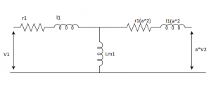
b) 
c) 
d) 
Answer: a
Explanation: When referred to primary, secondary inductance winding will be turns ratio squared.
13. Consider a 10 KVA, 2000/200 V, single phase transformer having below following parameters are r1=10Ω, r2=0.1Ω, l1 = 40mH, l2=0.4 mH, M = 10H. Then the expected primary self inductance will be?
a) 100.04H
b) 99.06H
c) 1.0004H
d) 10.04H
Answer: a
Explanation: Primary self inductance = L1 = Lm1 + l1
= (N1/N2)*M + l1
= 2000/200*10 + 0.04
=100.04 H.
Starting Of Induction Machines MCQs
14. There is a 10 KVA, 2000/200 V, single phase transformer having below following parameters are r1=10Ω, r2=0.1Ω, l1 = 40mH, l2=0.4 mH, M = 10H. Then the expected secondary self inductance will be?
a) 100.04H
b) 99.06H
c) 1.0004H
d) 10.04H
Answer: c
Explanation: Secondary self inductance = L2 = Lm2 + l2
= (N2/N1)*M + l2
= 200/2000*10 + 0.0004H
= 0.0004 H.
15. There is a 10 KVA, 2000/200 V, single phase transformer operating at 50 Hz. Maximum flux linkages in secondary will be?
a) 0.9 AT
b) 9 AT
c) 1 AT
d) 0.09 AT
Answer: a
Explanation: Flux linkages on secondary = N*φ = E/(4.44*f)
= 200/(4.44*50) = 0.9 AT
16. A 10 KVA, 2000/200 V, single phase transformer operating at 50 Hz with a current of 50 A flowing through the l.v. winding. Then the Self inductance of l.v. winding is?
a) 12.7mH
b) 1.27 mH
c) 12.7H
d) 0.127 H
Answer: a
Explanation: Flux linkages on l.v. = N*φ = E/(4.44*f)
= 200/(4.44*50) = 0.9 AT
Self inductance = mutual flux linkage/peak current
= 0.9/(1.414*50)
= 0.0127 H.
Three Phase Transformers
1. A V-V connected transformer can be connected in parallel to delta-delta connected transformer but not to ___________
a) delta-star
b) star-delta
c) star-V
d) all of the mentioned
Answer: a
Explanation: The V-V connected transformer and D-D connected transformers have same phase displacement, so they only can be connected in parallel to each other.
2. Three units of single phase transformers and one single three-phase transformer rating ___________
a) will be same for one rating
b) can never be made same
c) may be same
d) none of the mentioned
Answer: a
Explanation: Three single phase transformers and one single unit of three phase transformer will be same only. this is done to reduce the cost and spacing.
3. The transformer which is more feasible to use in the distribution ends should be ___________
a) star-delta
b) delta-star
c) scott
d) delta-delta
Answer: a
Explanation: Star-delta will have lower voltage at delta end.
4. For the given circuit below, the voltage across the terminal ‘a’ and ‘b’ is?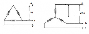
a) 1.73*V
b) V/1.73
c) V
d) 3*V
Answer: a
Explanation: From delta to star, the voltage between the lines will increase by 1.73.
5. The voltage across the terminal ‘r’ and ‘y’ is?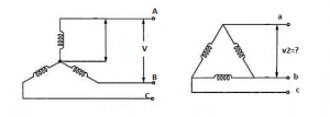
a) 1.73*V
b) V/1.73
c) V
d) 3*V
Answer: b
Explanation: From star to delta, the line voltage will reduce by 1.73.
6. The delta-delta connections are used in applications of ___________
a) large l.v. transformers
b) small h.v. transformers
c) large h.v. transformers
d) small l.v. transformers
Answer: a
Explanation: Delta connected winding handle line voltages so it needs more turns in the winding but thin wires.
7. Open delta transformers can be obtained from ___________
a) delta-delta
b) star-delta
c) delta-star
d) any of the mentioned
Answer: a
Explanation: If one of the transformers is removed from the bank of only delta-delta, then it behaves with 58% power delivery.
8. If one of the transformers is removed from the bank of only delta-delta, then it behaves with 58% power delivery.
a) True
b) False
Answer: a
Explanation: It is true as the circuit will still be closed and the transformer will operate will lesser operating point.
9. Below is the circuit diagram for delta-delta transformer have a transformation ratio ‘k’. The current flowing in the windings of phase r-y in the below diagrams is?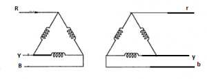
a) k*I/1.73
b) I/k*1.73
c) 1.73*k*I
d) 3*k*I
Answer: a
Explanation: The phase current will be reduced by 1/1.73.
10. If para magnetic core is used in the place of the ferromagnetic core of the transformer, then magnetostriction will ___________
a) be vanished
b) reduce
c) increase
d) not be affected
Answer: a
Explanation: If the core is not ferromagnetic then the transformer will not operate at all so no humming sound.
11. When we magnetize the ferromagnetic core of the transformer, core length_______ and it ______ when demagnetized.
a) decreases, increases
b) decreases, decreases
c) increases,increases
d) none of the mentioned
Answer: a
Explanation: Due to aligned magnetic dipoles in the material, the size will reduce by a small margin and vice versa while demagnetization.
12. A 400 V, 10 KVA transformer at 50 Hz, is operated at the frequency of 40 Hz, then the humming ___________
a) increases
b) decreases
c) remains same
d) increases to very high
Answer: a
Explanation: If the frequency is reduced, the core flux density increases, so the noise also will increase.
13. While using three phase transformers, it is taken care about the third harmonics current in the system. This is present when transformer set is delta on either side.
a) True
b) False
Answer: a
Explanation: Third harmonic current are co-phase in nature and require closed path which is present in delta connected only.
14. A recording of the output of the emf induced for star and delta are recorded. Then shape of the emf induced in Y-connected 3-phase transformer is non sinusoidal in nature due to ___________
a) 3rd harmonic component of currents is absent
b) 3rd harmonic component of currents is present
c) negative sequence component of current is present
d) none of the mentioned
Answer: a
Explanation: In a star connected transformer, closed path to generate 3rd harmonic is not there. So the emf shape will be peaky in nature.
15. Shape of emf generated by delta connected transformer is not always sinusoidal.
a) True
b) False
Answer: b
Explanation: No, for a delta transformer, closed path is present to generate 3rd harmonics current and so the emf will be sinusoidal always.
Autotransformers
1. While comparing potential transformer to an auto transformer, a potential transformer transfers power ________
a) conductively
b) inductively
c) both conductively as well as inductively
d) electromagnetic induction
Answer: a
Explanation: Potential divider is resistance division and it does not take part in induction processes.
2. The statements which support the points that auto transformers are advantageous?
I. Weight of conductor reduces
II. Ohmic losses reduces
III. Leakage reactance reduces
IV. Lower short-circuit current
a) I, II, III
b) II, III, IV
c) I, II, III, IV
d) I, IV
Answer: a
Explanation: Short circuit current of the auto transformer is higher than the corresponding 2-winding transformer.
3. The statements which support the points that auto transformers are advantageous?
I. Weight of conductor reduces
II. Direct electrical contacts
III. Leakage reactance reduces
IV. Lower short-circuit current
a) I, III
b) II, III
c) I, II, III, IV
d) I, IV
Answer: a
Explanation: Direct electrical contacts is a disadvantage to the auto transformer.
Short circuit current of the auto transformer is higher than the corresponding 2-winding transformer.
4. The statements which support the points that auto transformers are disadvantageous as compared to 2-winding transformer?
I. Weight of conductor reduces
II. Direct electrical contacts
III. Leakage reactance reduces
IV. Lower short-circuit current
a) I, III
b) II, III
c) II, IV
d) I, II, IV
Answer: c
Explanation: Direct electrical contacts is a disadvantage to the auto transformer.
Short circuit current of the auto transformer is higher than the corresponding 2-winding transformer.
5. Which of the above are correct for an auto transformer when compared to the identical rating two winding transformer?
I. KVA rating : 1/(1-k)
II. Losses : (1-k)
III. Impedance drop = 1/(1-k)
a) I, II
b) II, III
c) 1, III
d) I, II, III, IV
Answer: a
Explanation: KVA(auto)/KVA(2-W) = V2*I2/V2*(I2-I1)
= 1/(1-I1/I2)
= 1/(1-k)
Losses(auto) = (1-k) *Losses(2-W)
Impedance drop(auto) = (1-k)*Impedance drop(2-W).
6. The voltage regulation of a transformer at full-load 0.8 p.f leading is -2%. Its voltage regulation at full load 0.8 p.f lagging _____________
a) will be positive
b) will be negative
c) may be positive
d) may be negative
Answer: a
Explanation: The leading p.f. has negative v.r. and lagging p.f. has major portion of positive voltage regulation.
7. The voltage regulation of a transformer depends on its __________
(A) Equivalent reactance
(B) Equivalent resistance
(C) Load power factor
(D) Transformer size
(E) Load current
a) A, B, C, E
b) A, B, C, D, E
c) A, B, D, E
d) A, B, C, D
Answer: a
Explanation: Voltage regulation is independent of the size of the transformer.
8. Three transformers having identical dimensions but with core of iron, aluminium and wood are wound with same number of turns and have same supply. Then choose the order for hysteresis losses.
a) wood > aluminium > iron
b) aluminium > iron > wood
c) iron > wood > aluminium
d) iron > aluminium > wood
Answer: d
Explanation: Hysteresis losses occur maximum in the ferromagnetic material.
9. Three transformers having identical dimensions but with core of iron, aluminium and wood are wound with same number of turns and have same supply. Then choose the order for eddy current losses.
a) wood > aluminium > iron
b) aluminium > iron > wood
c) iron > wood > aluminium
d) iron > aluminium > wood
Answer: a
Explanation: The eddy current losses are dependent on resistance offered to the currents. Wood is an insulator so it will get heated up most.
10. Maximum efficiency of a transformer for a constant load current, occurs at __________
a) at any p.f
b) zero p.f leading
c) zero p.f lagging
d) unity p.f
Answer: d
Explanation: Efficiency = KVA*p.f/(KVA*p.f + Losses); So the efficiency is maximum at unity power factor.
11. A 1-phase tranformer has a leakage impedance of 1+ j4 Ω for primary and 3+ j11 Ω for secondary windings. This transformer has __________
a) H.V primary
b) Medium voltage primary
c) L.V primary
d) L.V secondary
Answer: c
Explanation: The side which has lower impedance will have lower number of turns and so the low voltage side.
12. If a transformer is at no load, then it will act like __________
a) a resistor at p.f = 0
b) an inductive reactor at 0.2 lagging
c) a capacitive reactor at0.2 leading
d) an inductive reactor at 0.8 lagging
Answer: b
Explanation: Transformer is nothing but the arranged windings which are magnetically coupled. The windings will inductive predominantly with very low resistance.
13. The tappings on the transformers is provided on __________
a) h.v side at one end of the winding
b) l.v. side at one end of the winding
c) h.v side at middle
d) l.v side at middle
Answer: c
Explanation: High voltage side winding has more voltage so the variation of the voltage will be more and better applicable. And it is better to place at the middle because it gives uniform voltage distribution by eliminating axial forces.
14. In a transformer, we place the tapping windings at the middle because __________
a) of radial forces on the windings
b) axial forces on the windings
c) insulation level of the winding
d) to provide a mechanical balance to the windings
Answer: b
Explanation: Due to two different voltages, different currents will flow in the windings and it will cause the axial forces due to currents interaction appear causing damage.
15. When a transformer winding suffers a short circuit, then inter turns of the same winding experience ______ forces.
a) an attractive
b) a repulsive
c) no force
d) may be attractive or repulsive type
Answer: a
Explanation: As the current will flow in one direction, attractive force will appear across the inter turns as per Biot-savart’s law.
16. Two tranformer having same voltage but different KVA are operating in parallel. For a good load sharing __________
a) impedance must be equal
b) pu impedances must be equal
c) pu impedance and X/R ratios must be equal
d) impedance and X/R ratios must be equal
Answer: c
Explanation: Both the conditions are to be met in order to have an efficient operation while in parallel condition.