Competitive Electric Circuits MCQs – Techniques of Circuit Analysis MCQs ( Electric Circuits ) MCQs

Latest Electric Circuits MCQs
By practicing these MCQs of Techniques of Circuit Analysis MCQs ( Electric Circuits ) MCQs – Latest Competitive MCQs , an individual for exams performs better than before. This post comprising of objective questions and answers related to “Techniques of Circuit Analysis MCQs ( Electric Circuits ) Mcqs “. As wise people believe “Perfect Practice make a Man Perfect”. It is therefore practice these mcqs of Electric Circuitsto approach the success. Tab this page to check “Techniques of Circuit Analysis MCQs ( Electric Circuits )” for the preparation of competitive mcqs, FPSC mcqs, PPSC mcqs, SPSC mcqs, KPPSC mcqs, AJKPSC mcqs, BPSC mcqs, NTS mcqs, PTS mcqs, OTS mcqs, Atomic Energy mcqs, Pak Army mcqs, Pak Navy mcqs, CTS mcqs, ETEA mcqs and others.
Techniques of Circuit Analysis MCQs ( Electric Circuits ) MCQs – Electric Circuits MCQs
The most occurred mcqs of Techniques of Circuit Analysis MCQs ( Electric Circuits ) in past papers. Past papers of Techniques of Circuit Analysis MCQs ( Electric Circuits ) Mcqs. Past papers of Techniques of Circuit Analysis MCQs ( Electric Circuits ) Mcqs . Mcqs are the necessary part of any competitive / job related exams. The Mcqs having specific numbers in any written test. It is therefore everyone have to learn / remember the related Techniques of Circuit Analysis MCQs ( Electric Circuits ) Mcqs. The Important series of Techniques of Circuit Analysis MCQs ( Electric Circuits ) Mcqs are given below:
The Node-Voltage Method and Dependent Sources and Some Special Cases
1. Nodal analysis is mainly based on __________
a) KCL
b) KVL
c) Wheatstone bridge principle
d) Faraday’s electric laws
Answer: a
Explanation: Nodal analysis or Node-Voltage method is done by identifying the currents at the node and thereby forming equations.
2. If there are n nodes, then how many node-voltage equations are required?
a) n
b) n+1
c) n-1
d) 1
Answer: c
Explanation: If there are n nodes then n-1 nodal equations are required to describe the circuit.
3. Find VA and VB using Node-Voltage method in the given circuit.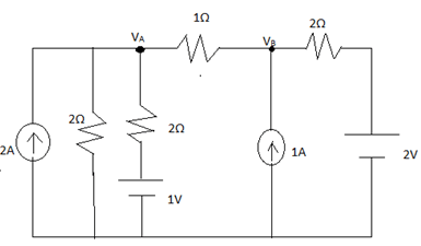
a) 2.5V, 3.6V
b) 2.87V, 3.25V
c) 2.65V, 3.47V
d) 3.15V, 2.76V
Answer: b
Explanation: Node A: VA/2 + (VA-1)/2 + (VA-VB)/1 =2
Node B: (VB-2)/2 + (VB-VA)/1 =1
By solving the above equations required voltages are obtained.
4. A supernode is between _____________
a) Essential node and reference node
b) Two reference nodes
c) Two essential nodes
d) Essential node and neutral path
Answer: c
Explanation: A supernode is between two essential nodes.
5. Find V3 in the circuit given below.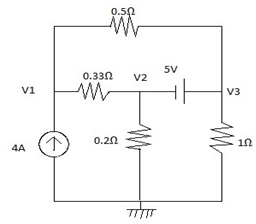
a) 4.833V
b) 2.616V
c) -4.833V
d) -2.616V
Answer: a
Explanation: supernode: V3-V2 = 5V
Node1: 166V1-100V2-66V3 =132
Node3: -166V1+265V2+99V3 =0
On solving the required voltage is obtained.
6. Find all the node voltages in the given circuit containing dependent sources.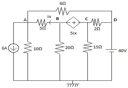
a) 10V, 20V, 30V, 40V
b) 15V, 25V, 32V, 45V
c) 10V, -20V, 30V, -40V
d) -15V, 25V, -35V, 45V
Answer: a
Explanation: At supernode: VC-VB=5iX
And ix = (VB-VA)/5. On solving remaining nodes and forming equations, the required voltage values at nodes are obtained.
7. What is the voltage at 2nd terminal in the given circuit?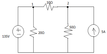
a) 132.57V
b) 137.25V
c) 173.25V
d) 123.57V
Answer: b
Explanation: Given voltage source 135V is in between essential node and reference node. So that implies V1 =135V. Using this, V2 can be calculated.
8. If there are 5 nodes then the no of nodal equations are ___________
a) 5
b) 0
c) 1
d) 4
Answer: d
Explanation: If there are n nodes then n-1 nodal equations are required to describe the circuit.
9. If there are (N-2+3) Node-Voltage equations then the number of nodes in the circuit are __________
a) N+2
b) N+1
c) N
d) N-1
Answer: a
Explanation: If there are n nodes then n-1 nodal equations are required to describe the circuit. So, given N-2+3 i.e. N+1 nodal equations and it implies N+2 nodes.
10. The reference node is also known as __________
a) Essential node
b) Principle node
c) Datum node
d) Neutral node
Answer: c
Explanation: The node taken for reference in the network is known as reference node or datum node.
11. If there are 9 nodes, then how many node-voltage equations are required?
a) 9
b) 10
c) 8
d) 1
Answer: c
Explanation: If there are n nodes then n-1 nodal equations are required to describe the circuit.
12. There are 13 branches in a complicated network and nearly 8 nodes. How many equations are required to solve the circuit in node-voltage method?
a) 7
b) 13
c) 5
d) 6
Answer: a
Explanation: Branches number is not required in this method. Only nodes number is required.
The Mesh-Current Method and Dependent Sources and Some Special Cases
1. The loop which does not contain any other inner loop is known as _____________
a) A node
b) A mesh
c) A branch
d) A super mesh
Answer: b
Explanation: A mesh is defined as a loop which does not contain any other loop within it.
2. If there are 6 branches and 4 essential nodes, how many equations are required to describe a circuit in mesh-current method?
a) 3
b) 6
c) 4
d) 2
Answer: a
Explanation: In Mesh-Current method, b-(n-1) equations are required to describe the circuit. b= the number of branches and n= the number of essential nodes.
3. Find the current flowing through 5Ω resistor in the given circuit.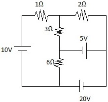
a) 0.57A
b) 0.64A
c) 0.78A
d) 0.89A
Answer: c
Explanation: There are 3 meshes in the given circuit. Assuming currents I1, I2, I3 in the 3 meshes and by applying KVL, equations will be obtained which on solving gives the respective currents flowing in the circuits.
4. A Super Mesh analysis could be done when there is a common _____________ between any two loops.
a) Voltage source
b) Current source
c) Resistor
d) Both voltage and current source
Answer: b
Explanation: A Super Mesh analysis could be done when there is a common current source between any two loops.
5. Calculate the current flowing through 10Ω resistor in the circuit shown below.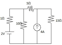
a) ±0.435A
b) ±0.985A
c) 1.217A
d) 2.782A
Answer: a
Explanation: Loop2 and loop3 forms a supermesh.
Supermesh: I3-I2=4
Loop1: 11I1-10I2=2
KVL at Supermesh: -2I1+3I2+3I3=0
Solving these gives the currents flowing in the circuit and current through 10Ω resistor is either I1-I2 or I2-I1.
6. Find the power delivered by the voltage source in the network given below.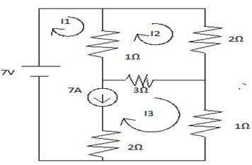
a) 65Watts
b) 72Watts
c) 63Watts
d) 76Watts
Answer: c
Explanation: 3 loops and a supermesh between loop1 and loop3. Using KVL currents are found out. I1=9A, I2=2.5A, I3=2A. As voltage source is in 1st loop, Power delivered by voltage source=V*I1.
7. The Mesh-Current method is applicable only for ___________
a) Non-linear networks
b) Equivalent networks
c) Non-planar networks
d) Planar networks
Answer: d
Explanation: The Mesh-Current method is applicable only for Planar networks. A network is said to be planar if there are no crossovers in it and it can be drawn freely on a plane surface.
8. Find the value of VX in the circuit given below.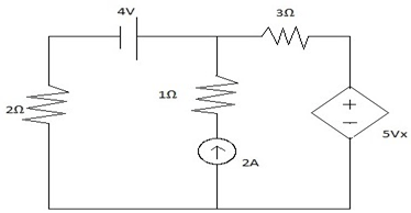
a) –0.8A
b) +0.8A
c) -4.8A
d) +4.8A
Answer: a
Explanation: Applying KVL, currents could be found out. I1=0.4A, I2=2.4A. VX=-I1R1.
9. A Supermesh is formed between two loops which share a common voltage source.
a) True
b) False
Answer: b
Explanation: Meshes that share a current source with other meshes, none of which contains a current source in the outer loop, forms a supermesh.
10. If 4 equations are required to describe a circuit by Mesh-Current method and there are n nodes. How many branches are there in the network?
a) n+5
b) n+3
c) n
d) n-1
Answer: b
Explanation: Standard formulae: b-(n-1)
Given b-(n-1) =4 -> b=4+ (n-1) =n+3.
11. If there are 16 branches and 5 essential nodes, how many equations are required to describe a circuit in mesh-current method?
a) 12
b) 16
c) 21
d) 9
Answer: a
Explanation: In Mesh-Current method, b-(n-1) equations are required to describe the circuit. b=the number of branches and n= the number of essential nodes.
12. Determine the current through 3Ω resistor in the network given below.
a) 2A
b) 3A
c) 4A
d) -2A
Answer: c
Explanation: Mesh1 and Mesh2 form a super mesh. Assuming currents I1 and I2 and applying KVL, the current through required resistor is found out.
13. Mesh analysis is best suitable for _____________
a) Current sources
b) Voltage sources
c) Complex elements
d) Unilateral elements
Answer: a
Explanation: Mesh analysis is best suitable for Current sources.
The Node-Voltage Method Versus the Mesh-Current Method
1. Which method is best for voltage sources?
a) Mesh analysis
b) Nodal analysis
c) Superposition principle
d) Differentiation method
Answer: b
Explanation: Every voltage source connected to the reference node reduces the equations to be solved. Thus, the node-voltage method is best for voltage sources.
2. When there is a current source between two loops which method is preferred?
a) Mesh-voltage analysis
b) Node-current analysis
c) Supermesh
d) Supernode
Answer: c
Explanation: Supermesh is taken into consideration when there is a current source n between two loops and is considered as one single loop.
3. Determine the current through 5Ω resistor in the network given below.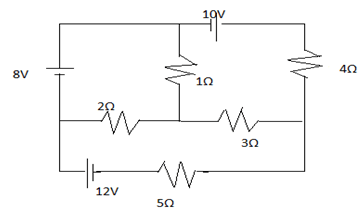
a) 3.38A
b) 6.01A
c) 3.27A
d) 1.27A
Answer: a
Explanation: This problem can be solved quickly by using the mesh-current method. 3loops=3 KVL equations. Solving them gives respective currents.
4. Find the power supplied by the dependent voltage source in the circuit given below.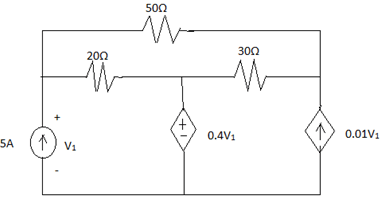
a) 400W
b) 383W
c) 412W
d) 148W
Answer: b
Explanation: 3loops=3KVL equations. Solving them gives currents flowing in the circuit. I1=5A, I2=-1.47A, I3=0.56A .Power supplied by dependent voltage source =0.4V1 (I1-I2).
Inductance, Capacitance And Mutual Inductance MCQs
5. Determine the voltage V2 of the network given.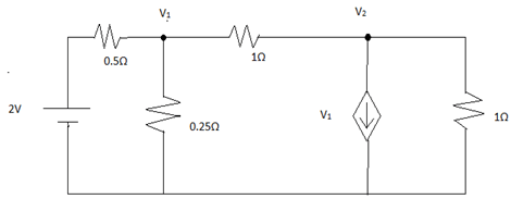
a) 0V
b) 1V
c) 4/7V
d) -4/7V
Answer: a
Explanation: As there are voltage sources and nodes, node-voltage method is best suitable. Solving gives V1 =4/7V and V2=0 (since there is no voltage source near node2).
6. If there are b branches and n nodes, then how many node-voltage equations are required?
a) n
b) b+1
c) n-1
d) b
Answer: c
Explanation: If there are n nodes then n-1 nodal equations are required to describe the circuit. Branches do nothing in this case.
7. There are 6 branches and 2 essential nodes then 3 equations are required to describe a circuit in the mesh-current method.
a) True
b) False
Answer: b
Explanation: In Mesh-Current method, b-(n-1) equations are required to describe the circuit. b= the number of branches and n= the number of essential nodes. So, 6-(2-1) =5.
8. Determine V1 of the given network.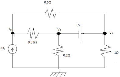
a) -0.17V
b) 4.83V
c) 5V
d) 2.62V
Answer: d
Explanation: Supernode: V3-V2=5. Applying KCL at node1 and at supernode gives the equations which on solving, required voltages are obtained.
9. When there is a voltage source between two nodes which method is preferred?
a) Mesh-voltage analysis
b) Node-current analysis
c) Supermesh
d) Supernode
Answer: d
Explanation: Supernode is taken into consideration when there is a voltage source n between two nodes.
10. Which is the best-preferred method to calculate currents flowing in the circuit?
a) Mesh-voltage analysis
b) Node-current analysis
c) Superposition principle
d) Duality principle
Answer: a
Explanation: By KVL, currents can be easily found out in mesh-voltage method.
Source Transformations
1. By using source transformation voltage source in series resistor is replaced by __________
a) Voltage source in series with a resistor
b) Current source in parallel with a resistor
c) Voltage source in parallel with a resistor
d) Current source in series with a resistor
Answer: b
Explanation: In Source transformation, a voltage source in series with a resistor is replaced by a current source in parallel with the same resistor and vice versa.
2. Source Transformation is _____________
a) Unilateral
b) Unique
c) Bilateral
d) Complicated
Answer: c
Explanation: In Source transformation, a voltage source in series with a resistor is replaced by a current source in parallel with the same resistor and vice versa. So, it is bilateral.
3. If there are two resistors in parallel and in series with a voltage source then ___________
a) Parallel resistor has no effect
b) Series resistor has no effect
c) Both has their respective effects
d) Both has no effect on the voltage source
Answer: a
Explanation: In source transformation, the voltage source in series with a resistor to be replaced by a current source in parallel with the same resistor and vice versa. So other resistors are redundant and have no effect.
4. Using source transformation, calculate the voltage.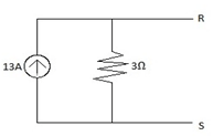
a) 4.33V
b) 39V
c) 0.230V
d) 36V
Answer: b
Explanation: V=IR=13*3=39V.
5. Which element(s) has no effect in the given circuit?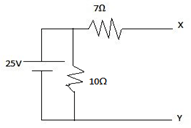
a) 7Ω
b) 10Ω
c) Both 7Ω and 10Ω
d) Voltage source.
Answer: b
Explanation: Voltage in series with a resistor in replaced by a current source but here 10Ω is in parallel. So, it is redundant and has no effect.
6. The value of current source is __________ after replacing the given network with a single current source and a resistor.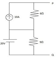
a) 70V
b) 60V
c) 90V
d) 80V
Answer: d
Explanation: In the given circuit 9Ω resistor has no effect.
10*6=60V, 60V+20V=80V.
7. If there is a 12A current source in series with 2Ω and in parallel with a 4Ω resistor, then voltage V=?
a) 24V
b) 48V
c) 3V
d) 6V
Answer: b
Explanation: 2Ω resistor is redundant. 12*4=48V.
8. Find the current flowing through 4Ω resistor shown in network below.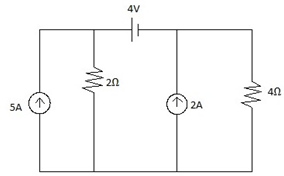
a) 1.33A
b) 2.35A
c) 1.66A
d) 2.66A
Answer: c
Explanation: By using source transformation the above network is reduced and then by current division rule I4Ω= 5*(2/2+4) =1.66A.
9. Calculate the power delivered by the 50V source.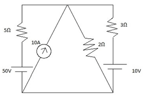
a) 274W
b) 276W
c) 285W
d) 291W
Answer: a
Explanation: By using source transformation the above network is reduced and current in the circuit is found out and later power delivered by 50V source= 50*current in the circuit= 50*5.48A= 274W.
10. Source transformation can be used for dependent sources.
a) True
b) False
Answer: a
Explanation: Source transformation can be used for dependent sources. However, the controlling variable must not be tampered with any way since the controlled source operation depends on it.
11. Using source transformation, calculate vm.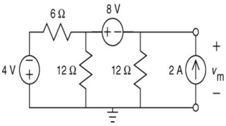
a) 2v
b) -2v
c) 1v
d) -1v
Answer: b
Explanation: Using source transformation, the network is reduced and at last voltage is obtained.
12. Find the voltage value Vm in the circuit given below.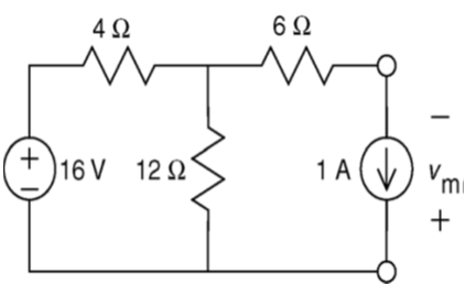
a) -3V
b) 3V
c) 2.1V
d) -2.1V
Answer: a
Explanation: Using source transformation, the voltage source in series with a resistor to be replaced by a current source in parallel with the same resistor and vice versa.
13. Source transformation technique is mainly based on __________ law.
a) Newton’s
b) Kirchhoff’s
c) Ohm’s
d) Einstein’s
Answer: c
Explanation: Ohm’s law: V=iR. By using this, the voltage/ current sources are reduced.
14. In source transformation,
a) Voltage sources remain same
b) Current sources remain same
c) Both voltage and current sources undergo change
d) Resistances/Impedances remain same
Answer: d
Explanation: In source transformation, only the particular voltage/current sources change whereas the resistances remain same.
15. If there are five 20V voltage sources in parallel, then in source transformation __________
a) All are considered
b) Only one is considered
c) All are ignored
d) Only 2 are considered
Answer: b
Explanation: In parallel, voltages are same. So, only is considered and rest are ignored.
Thevenin and Norton Equivalents, More on Deriving a Thevenin Equivalent
1. Find the voltage across 24Ω resistor by using Thevenin’s theorem.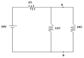
a) 8V
b) 9V
c) 1V
d) 6V
Answer: a
Explanation: 1. Remove 24Ω resistor and calculate the voltage across the open circuit.
2. Calculate the thevenin’s resistance and by using it, the thevenin’s current.
3. V24Ω=I*R (can also verify by using Nodal analysis).
2. Calculate Thevenin’s voltage for the network shown below where the voltage source is 4V.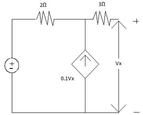
a) 6V
b) 4.71V
c) 5V
d) 1V
Answer: c
Explanation: In the circuit given, thevenin’s voltage is nothing but the open circuit voltage which is Vx. Applying KVL, it is obtained.
3. Find the Thevenin’s resistance for the network given.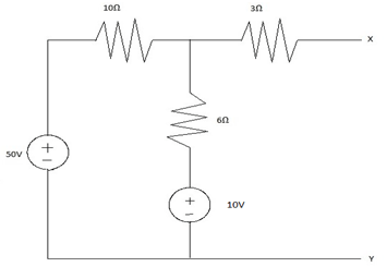
a) 6.75Ω
b) 5.85Ω
c) 4.79Ω
d) 1.675Ω
Answer: a
Explanation: Remove all the voltage/current sources and calculate the equivalent resistance.
4. Find the current through (5+j4) Ω resistor.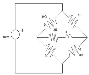
a) 0.9-j0.2 A
b) 0.78-j0.1 A
c) 2.7-j0.5 A
d) 1A
Answer: a
Explanation: 1. Remove the 5+j4 Ω branch and calculate thevenin’s voltage.
(V= v across 6Ω resistor- v across 8Ω resistor)
2. Calculate Zth. (10//6 and 8//8)
3. Current= (Vth/ (Zth+Z).
5. The voltage across 6Ω resistor is __________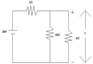
a) 7.5V
b) 6.78V
c) 20V
d) 8.5V
Answer: d
Explanation: Remove the resistor across which voltage is to be calculated and short circuit it. By using short circuit current and resistance calculate the current across 6Ω resistor and thereby voltage. (In this 10Ω resistor is also short-circuited since 10//0).
6. Find the Norton’s current for the circuit given below.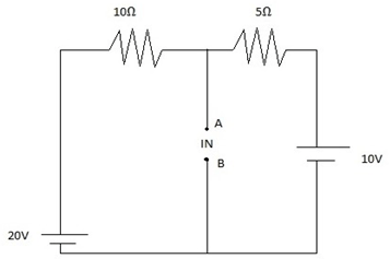
a) 5A
b) 3.33A
c) 4A
d) 1.66A
Answer: c
Explanation: IN= (20/10) + (10/5).
7. Calculate IN for the given network.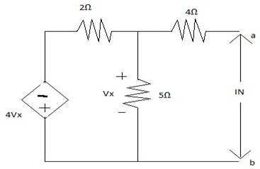
a) 0A
b) 1A
c) 4.37A
d) 0.37A
Answer: a
Explanation: Using nodal analysis Vx is calculated. IN =Vx/4.
8. Calculate RTh for the network given.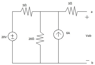
a) 8Ω
b) 7Ω
c) 2Ω
d) 1Ω
Answer: b
Explanation: 5//20 and then in series with 3Ω resistor.
9. Thevenin’s equivalent circuit consists of a ____________
a) Voltage source in series with a resistor
b) Current source in parallel with a resistor
c) Voltage source in parallel with a resistor
d) Current source in series with a resistor
Answer: a
Explanation: Thevenin’s equivalent circuit contains a Voltage source in series with a resistor.
10. Norton’s equivalent circuit consists of a _____________
a) Voltage source in series with a resistor
b) Current source in parallel with a resistor
c) Both voltage and current sources
d) Current source in series with a resistor
Answer: b
Explanation: Norton’s equivalent circuit consists of a Current source in parallel with a resistor.
11. Thevenin’s voltage is equal to ____________
a) Short circuit voltage
b) Open circuit current
c) Open circuit voltage
d) Short circuit current
Answer: c
Explanation: Thevenin’s voltage is equal to open circuit voltage.
12. Norton’s current is equal to ____________
a) Short circuit voltage
b) Open circuit current
c) Open circuit voltage
d) Short circuit current
Answer: d
Explanation: Norton’s current is equal to Short circuit current.
13. Thevenin’s resistance RTh = ___________
a) VTh/ISC
b) VSC/ITh
c) VTh/ITh
d) VSC /ISC
Answer: a
Explanation: Thevenin’s resistance is defined as the ratio of open circuit voltage to the short circuit current across the terminals of the original circuit.
14. What is the expression forthe thevenin’s current if there is an external resistance in series with the RTh?
a) VTh/ITh
b) VTh/ (RTh-R)
c) VTh/ (RTh+R)
d) VTh/RTh
Answer: c
Explanation: ITh= VTh/ (RTh+R).
15. One can find the thevenin’s resistance simply by removing all voltage/current sources and calculating equivalent resistance.
a) False
b) True
Answer: b
Explanation: Yes. One can find the thevenin’s resistance simply by removing all voltage/current sources and calculating equivalent resistance.
Maximum Power Transfer and Superposition
1. Which of the following is the example to describe the efficiency of power transfer?
a) Communication systems
b) Power utility systems
c) Instrumentation systems
d) Telecom systems
Answer: b
Explanation: Power utility systems are good examples for this case as they are concerned with the generation, transmission and distribution of power in large quantities.
2. In a network maximum power transfer occurs when __________
a) RTh= -RL
b) RTh/RL =0
c) RTh= RL
d) RTh+RL= 1
Answer: c
Explanation: Maximum power transfer occurs when load resistance equals the thevenin’s resistance.
3. Maximum power in terms of the thevenin’s voltage and load resistance __________
a) (VTh) 2 /4RL
b) (VTh) 2 *4RL
c) (VTh) 2 +4RL
d) 4RL/ (VTh) 2
Answer: a
Explanation: Pmax= v*i= i*R*i= i2RL = (VTh/(RTh+RL))2*RL. Max power occurs when RL=RTh.
4. Calculate the maximum power delivered across RL of the circuit given.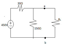
a) 900W
b) 1025W
c) 2025W
d) 1500W
Answer: c
Explanation: Pmax= (VTh/(RTh+RL))2*RL (RTh=RL)
VTh= (150/150+30)*540= 450V
RTh=(150*30)/180= 25Ω (the given resistors are in parallel).
5. Determine the maximum power delivered to the load in the network given.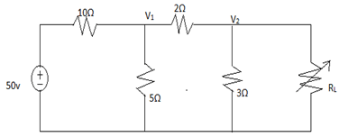
a) 4.68W
b) 5.75W
c) 3.16W
d) 6.84W
Answer: a
Explanation: Load is given across node V2 and reference path. It implies the thevenin’s voltage is V2. By using nodal analysis this voltage is found out.
RTh=RL= 10Ω//5Ω and in series with 2Ω and then parallel with 3Ω=1.92Ω
Max power = (VTh) 2 /4RL = 4.688W.
6. The Superposition principle is obeyed by ____________
a) Linear networks
b) Non-linear networks
c) Lateral networks
d) Trilateral networks
Answer: a
Explanation: A linear system obeys Superposition Principle. In a linear network parameters are constant i/e/ won’t change with voltage and current.
7. According to Superposition principle response in one element is the algebraic sum of responses by individual sources acting alone.
a) False
b) True
Answer: b
Explanation: According to Superposition principle response in one element is the algebraic sum of responses by individual sources acting alone while other sources are non-operative.
8. Find the current in the 3Ω resistor of the given network using Superposition principle.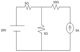
a) 2.5A
b) 3.125A
c) 6.525A
d) 5.625A
Answer: d
Explanation: 1.When 20v source acting alone: current source is replaced by open circuit. Req= 5+3=8Ω and Current I= 20/8=2.5A
2. When 5A source acting alone: 20v source is replaced by a short circuit. By current division rule, I3= 25/8=3.125A
Total current through I3= 2.5+3.125=5.625A.
9. Find the current in 5Ω resistor near 12V source using superposition principle in network given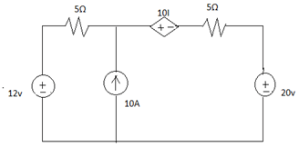
a) 2.9A
b) -2.9A
c) 1A
d) -1A
Answer: b
Explanation: Only 3 sources are considered (12V, 10A, 20V), other is dependent (10I).
12v source: I=0.6A
10A source: I=-2.5A through 5Ω resistor and I=7.5A
20v source: I=-1A
Total current = 0.6+ (-2.5) + (-1) = -2.9A.
10. If there are 5 sources in a network out of which 3 are dependent and 2 are independent. For superposition principle ___________ sources are considered.
a) 5
b) 3
c) 2
d) 0
Answer: c
Explanation: Only independent sources are considered while using Superposition principle. Dependent sources are never deactivated while using this principle.
11. Find the current in the 1Ω resistor of the given circuit.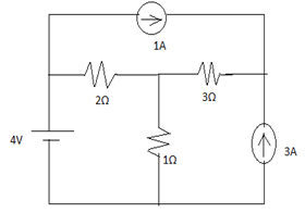
a) 4A
b) 1.33A
c) 2A
d) 0.66A
Answer: a
Explanation: when all the sources are acting alone the corresponding currents are found out using current division rule and finally all are summated to get the required current through the1Ω resistor. (Current = 1.33+0.66+2=4A).
12. Find the value of RL in given circuit.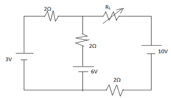
a) 4Ω
b) 5Ω
c) 3Ω
d) 1.66Ω
Answer: c
Explanation: RTh=RL= (2//2) + 2=3Ω.
13. Calculate the maximum power delivered to load in the network given.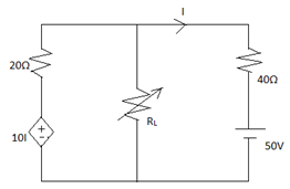
a) 1.56W
b) 1.66W
c) 2.33W
d) 2.79W
Answer: a
Explanation: 1.Calculation of VTh. (by using mesh analysis)
2. Calculation of Norton’s current.
3. Calculation of RTh. (RTh=VTh/IN)
4. RTh=RL and PMax= VTh/4RL.
14. In AC networks, maximum power is delivered when __________
a) ZL*ZS*=0
b) ZL+ZS*=1
c) ZL=-ZS*
d) ZL=ZS*
Answer: d
Explanation: Max power is delivered when load impedance equals complex conjugate of the source impedance.
15. Superposition principle states that at a time __________ source(S) acts.
a) All the given sources
b) Only voltage sources
c) Only one source
d) Only current sources
Answer: c
Explanation: Only one source acts at a time. Remaining sources are non-operative during this period.
Competitive Electric Circuits MCQs – Techniques of Circuit Analysis MCQs ( Electric Circuits ) MCQs