Competitive Electrical Measurements MCQs – Extension of Instrument Ranges ( Electrical Measurements ) MCQs

Latest Electrical Measurements MCQs
By practicing these MCQs of Extension of Instrument Ranges ( Electrical Measurements ) MCQs – Latest Competitive MCQs , an individual for exams performs better than before. This post comprising of objective questions and answers related to “ Extension of Instrument Ranges ( Electrical Measurements ) Mcqs “. As wise people believe “Perfect Practice make a Man Perfect”. It is therefore practice these mcqs of Electrical Measurements to approach the success. Tab this page to check ” Extension of Instrument Ranges ( Electrical Measurements )” for the preparation of competitive mcqs, FPSC mcqs, PPSC mcqs, SPSC mcqs, KPPSC mcqs, AJKPSC mcqs, BPSC mcqs, NTS mcqs, PTS mcqs, OTS mcqs, Atomic Energy mcqs, Pak Army mcqs, Pak Navy mcqs, CTS mcqs, ETEA mcqs and others.
Electrical Measurements MCQs – Extension of Instrument Ranges ( Electrical Measurements ) MCQs
The most occurred mcqs of Extension of Instrument Ranges ( ) in past papers. Past papers of Extension of Instrument Ranges ( Electrical Measurements ) Mcqs. Past papers of Extension of Instrument Ranges ( Electrical Measurements ) Mcqs . Mcqs are the necessary part of any competitive / job related exams. The Mcqs having specific numbers in any written test. It is therefore everyone have to learn / remember the related Extension of Instrument Ranges ( Electrical Measurements ) Mcqs. The Important series of Extension of Instrument Ranges ( Electrical Measurements ) Mcqs are given below:
Shunts and Multipliers
1. Range of an electrical instrument depends on __________
a) current
b) voltage
c) power
d) resistance
Answer: a
Explanation: The amount of current safely passing through the coil of the instrument and the spiral springs. This acts as the leads of the current to the instrument. As a result, the range of an electrical instrument depends on the current.
2. Moving coil instruments have a current and voltage rating of __________
a) 100 A and 25 V
b) 50 mA and 50 mV
c) 75 nA and 100 μV
d) 25 μA and 75 V
Answer: b
Explanation: Moving coil instruments are designed to function as Ammeters and Voltmeters. They have a maximum current carrying capacity of 50 mA with a voltage rating of 50 mV.
3. A shunt is a __________
a) very high resistance
b) medium resistance
c) very low resistance
d) high resistance
Answer: c
Explanation: Usually shunt is a very low value of resistance. It is connected in parallel with the ammeter coil. Through this we can extend the range of an ammeter.
4. A shunt can be used to measure large currents.
a) True
b) False
Answer: a
Explanation: A shunt is normally a very low value of resistance, connected in parallel with the ammeter coil. By making use of a low range ammeter, large current values can be measured through a shunt.
5. Current terminals have a small current capacity.
a) True
b) False
Answer: b
Explanation: A shunt is normally a very low value of resistance, connected in parallel with the ammeter coil. In a shunt, the current terminals have a large current capacity and are connected in series.
6. Potential terminals have a __________
a) high current capacity
b) low voltage capacity
c) low current capacity
d) high voltage capacity
Answer: c
Explanation: A shunt is normally a very low value of resistance, connected in parallel with the ammeter coil. In a shunt, the potential terminals have a low current carrying capacity. As a result, a low range ammeter is used to measure the large current.
7. In case of AC ammeters, shunts consist of __________
a) impedance
b) capacitance
c) resistance
d) inductance
Answer: d
Explanation: AC ammeter shunts comprise of the inductances of the ammeter as well as the shunt. In order to extend the range of an AC ammeter, inductances of the ammeter and the shunt are taken into account.
8. What is the effect of the ammeter range on the shunt resistance?
a) no effect
b) varies by a factor of multiplying factor
c) varies by a factor of the resistance
d) varies by a factor of unity
Answer: b
Explanation: We know that
N = 1 + Ra⁄Rs
where, N is the multiplying factor
Ra is the ammeter resistance
Rs is the shunt resistance
It is clear from the above equation that in order to increase the ammeter range by N times, the shunt resistance is equivalent to 1⁄N-1.
9. A multiplier is __________
a) non-inductive
b) resistive
c) capacitive
d) non-capacitive
Answer: a
Explanation: A multiplier is basically a non-inductive, high resistance that is used to extend the range of a D.C. voltmeter. Multiplier consists of a low range D.C. voltmeter connected in series with it.
10. What is the condition for using a multiplier in A.C. voltmeters?
a) by using ac supply
b) by maintaining a uniform impedance
c) by maintaining a uniform frequency
d) by using a galvanometer
Answer: c
Explanation: A multiplier can be used for A.C. voltmeters. The condition to be satisfied is that the total impedance of the voltmeter and the multiplier circuit must be constant for a wide range of frequencies.
Instrument Transformers
1. What is the current transformer?
a) transformer used with an A.C. ammeter
b) transformer used with an D.C. ammeter
c) transformer used with an A.C. voltmeter
d) transformer used with an D.C. voltmeter
Answer: a
Explanation: A transformer used to extend the range of an A.C. ammeter is known as a current transformer. A current transformer is also abbreviated as C.T.
2. What is the potential transformer?
a) transformer used with an D.C. ammeter
b) transformer used with an A.C. voltmeter
c) transformer used with an D.C. ammeter
d) transformer used with an A.C. voltmeter
Answer: b
Explanation: A transformer used to extend the range of an A.C. voltmeter is known as a potential transformer. A potential transformer is also abbreviated as P.T.
3. C.T. and P.T. are used for _________
a) measuring low current and voltages
b) measuring very low current and voltages
c) measuring high currents and voltages
d) measuring intermediate currents and voltages
Answer: c
Explanation: C.T. is basically used for the measurement of high currents. A P.T. is usually used for the measurement of high voltages. They are used with A.C. ammeters and voltmeters in order to extend their range.
4. The primary winding of a C.T. has _________
a) a larger number of turns
b) no turns at all
c) intermediate number of turns
d) a few turns
Answer: d
Explanation: The primary winding of a C.T. has a very few number of turns. It is connected in series with the load circuit through which the primary current flows.
5. The secondary winding of a C.T. has _________
a) a large number of turns
b) a few turns
c) no turns at all
d) intermediate number of turns
Answer: a
Explanation: Secondary winding of a C.T. has a large number of turns. It is connected in series to an ammeter through which a small portion of the current flows through.
6. Turns ration for a C.T. is _________
a) n = Np ⁄ Ns
b) n = Ns ⁄ Np
c) n = 1 ⁄ Np
d) n = Ns
Answer: b
Explanation: The turns ratio for a C.T. is defined as the ratio of the number of turns in the secondary to the number of turns in the primary. It is given by the relation
n = Ns⁄Np
7. The primary winding of a P.T. has _________
a) intermediate number of turns
b) no turns at all
c) a larger number of turns
d) a few turns
Answer: c
Explanation: The primary winding of a P.T. has a very large number of turns. It is connected in parallel with the load whose voltage is to be measured.
8. The secondary winding of a P.T. has _________
a) a large number of turns
b) intermediate number of turns
c) no turns at all
d) a few turns
Answer: d
Explanation: Secondary winding of a P.T. has a few number of turns. A low range voltmeter is connected in parallel with the secondary winding.
9. Turns ration for a C.T. is _________
a) n = Np ⁄ Ns
b) n = Ns ⁄ Np
c) n = 1 ⁄ Np
d) n = Ns
Answer: a
Explanation: The turns ratio for a P.T. is defined as the ratio of the number of turns in the primary to the number of turns in the secondary. It is given by the relation
n = Np⁄Ns.
Measurement Of Inductance And Capacitance MCQs
Advantages of Instrument Transformers
1. Instrument transformers can be easily replaced.
a) True
b) False
Answer: a
Explanation: The secondary windings of C.T. and P.T. are standardized. As a result, instruments can be standardized with the ratings of C.T. and P.T. Hence the instrument transformers can be replaced with ease.
2. Instrument transformers provide _________
a) electrical isolation from low rated winding
b) electrical isolation from high rated winding
c) electrical isolation from medium rated winding
d) no electrical isolation at all
Answer: b
Explanation: In an instrument transformer, the low rated secondary windings provide electrical isolation from the high rated primary windings.
3. Instrument transformers give same readings irrespective of number of other instruments connected.
a) True
b) False
Answer: a
Explanation: When instruments are used with instrument transformers, they provide consistent readings. It does not vary with the instrument constants and the number of instruments connected in the circuit.
4. C.T. and P.T. are standardized at _________
a) 50 A and 220 V
b) 25 mA and 2.2 kV
c) 5 A and 110 V
d) 75 nA and 1.1 MV
Answer: c
Explanation: Current transformers are standardized at 5 A of secondary winding current, whereas Potential transformers are standardized at 110 V of secondary winding voltage.
5. A 5A ammeter can measure a current of upto 1000 A using a _________
a) 5/1000A C.T.
b) 1000A C.T.
c) 5A C.T.
d) 1000/5A C.T.
Answer: d
Explanation: A 1000/5A current transformer can be used for measuring a current of upto 1000A by making use of an ammeter with 5A current reading.
6. A 110V voltmeter can measure a voltage of upto 110kV using a _________
a) 110000/110V P.T.
b) 110000V P.T.
c) 110V P.T.
d) 110/110000V P.T.
Answer: a
Explanation: An 110000/110V potential transformer can be used for measuring a voltage of upto 110000V by making use of a voltmeter with 110V voltage reading.
7. How can the meter circuit be isolated from the power circuit?
a) by grounding
b) through electrical isolation
c) by physical separation
d) through mechanical isolation
Answer: b
Explanation: Leads of the secondary winding transformer are brought to the switch board thus separating them from high voltage windings. In this way, the meter circuit is isolated from the high voltage power circuit.
8. How are instrument transformers different from shunts and multipliers?
a) they are all the same
b) they have transformers
c) readings are independent of component values
d) they can be used for high voltages and currents
Answer: c
Explanation: Instrument transformers can be used for extending the range of the A.C. instruments. In instrument transformers, readings are independent of the values of R, L, and C. But in the case of shunts and multipliers, the readings depend on the values of circuit constants.
Ratios of Instrument Transformers
1. Transformation ratio of an instrument is defined as ____________
a) ratio of primary to secondary phasor
b) ratio of secondary to primary phasor
c) reciprocal of the primary phasor
d) reciprocal of the secondary phasor
Answer: a
Explanation: For an instrument transformer, the transformation ratio is defined as the ratio of the magnitude of the actual primary phasor to the magnitude of the secondary phasor.
2. For a C.T. the transformation ratio is given by which of the following relation?
a) R = IsIp
b) R = IpIs
c) R = 1Ip
d) R = Ip
Answer: b
Explanation: In a current transformer, the transformation ratio is given by the ratio of the magnitude of the actual primary current to the magnitude of the actual secondary current.
R = IpIs
where, R is the transformation ratio
Ip is the actual primary winding current
Is is the actual secondary winding current.
3. For a P.T. the transformation ratio is given by which of the following relation?
a) R = VsVp
b) R = 1Vs
c) R = VpVs
d) R = Vp
Answer: c
Explanation: In a potential transformer, the transformation ratio is given by the ratio of the magnitude of the actual primary current to the magnitude of the actual secondary current.
R = VpVs
where, R is the transformation ratio
Vp is the actual primary winding voltage
Vs is the actual secondary winding voltage.
4. Nominal ratio of an instrument transformer is defined as the __________
a) reciprocal of the rated primary value
b) ratio of rated secondary value to primary value
c) reciprocal of the rated secondary value
d) ratio of rated primary value to secondary value
Answer: d
Explanation: In an instrument transformer, nominal ratio is defined as the ratio of the rated primary current or voltage to the rated secondary winding current or voltage.
5. For a C.T. the nominal ratio is given by which of the following relation?
a) Kn = Ip(rated)Is(rated)
b) Kn = Is(rated)Ip(rated)
c) Kn = 1Is(rated)
d) Kn = Ip(rated)
Answer: a
Explanation: In a current transformer, the transformation ratio is given by the ratio of the magnitude of the actual primary current to the magnitude of the actual secondary current.
Kn = Ip(rated)Is(rated)
where, R is the transformation ratio
Ip(rated) is the rated primary winding current
Is(rated) is the rated secondary winding current.
6. For a P.T. the nominal ratio is given by which of the following relation?
a) Kn = Vs(rated)Vp(rated)
b) Kn = Vp(rated)Vs(rated)
c) Kn = 1Vs(rated)
d) Kn = Vp(rated)
Answer: b
Explanation: In a potential transformer, the transformation ratio is given by the ratio of the magnitude of the actual primary voltage to the magnitude of the actual secondary voltage.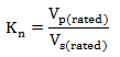
where, R is the transformation ratio
Vp(rated) is the rated primary winding voltage
Vs(rated) is the rated secondary winding voltage.
Measurement Of Resistance MCQs
7. Ratio correction factor is defined as _________
a) reciprocal of nominal ratio
b) ratio of nominal ratio to transformation ratio
c) ratio of transformation ratio to nominal ratio
d) reciprocal of transformation ratio
Answer: c
Explanation: The ratio correction factor for an instrument transformer is defined as the ratio of the transformation ratio to the nominal ratio.
R.C.F = R ⁄ Kn
where,
R.C.F is the ratio correction factor
R is the transformation ratio
Kn is the nominal ratio.
8. For a C.T. the turns ratio is defined as the _________
a) n = Np ⁄ Ns
b) n = 1 ⁄ Np
c) n = Ns
d) n = Ns ⁄ Np
Answer: d
Explanation: For a current transformer, the turns ratio is defined as the ratio of the number of turns in the secondary winding to the number of turns in the primary winding.
n = Ns ⁄ Np
where, n is the turns ratio
Ns is the secondary turns
Np is the primary turns.
9. For a P.T. the turns ratio is defined as the _________
a) n = Np ⁄ Ns
b) n = 1 ⁄ Np
c) n = Ns
d) n = Ns ⁄ Np
Answer: a
Explanation: For a potential transformer, the turns ratio is defined as the ratio of the number of turns in the primary winding to the number of turns in the secondary winding.
n = Np ⁄ Ns
where, n is the turns ratio
Np is the primary turns
Ns is the secondary turns.
Errors in Current Transformers
1. Errors are introduced in Current Transformers.
a) True
b) False
Answer: a
Explanation: A current transformer is used for the measurement of very high currents. The use of a C.T. leads to the introduction of two errors in power measurement.
2. Ratio error is defined as ___________
a) Ratio error = Kn⁄R
b) Ratio error = Kn – R⁄R
c) Ratio error = Kn – R
d) Ratio error = 1⁄R
Answer: b
Explanation: Ratio error of a C.T. is defined as the ratio of the magnitude of the difference between the nominal and actual ratio with respect to the actual ratio.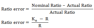
3. Phase angle in a C.T. is defined as ____________
a) 180π[ImcosδnIs] degrees
b) 180π[IcsinδnIs] degrees
c) 180π[Imcosδ–IcsinδnIs] degrees
d) 180π[Imsinδ–IccosδnIs] degrees
Answer: c
Explanation: During power measurement, there exists phase angle error in a C.T. The phase angle is defined as
Phase angle = 180π[Imcosδ–IcsinδnIs] degrees.
where. Im is the magnetising component of the excitation current
Ic is the core loss component of the excitation current
Is is the secondary winding current.
4. Phase angle error is given by ____________
a) 180π[1nIs] degrees
b) 180π[ImIs] degrees
c) 180π[Imn]degrees
d) 180π[ImnIs] degrees
Answer: d
Explanation: The power measurement in a C.T. leads to phase angle error. Phase angle error is given by the relation
θ = 180π[ImnIs] degrees
where, θ is the phase angle error
Im is the magnetising component of the excitation current
Is is the secondary winding current.
5. Ratio error is due to _________
a) iron loss
b) C.T.
c) magnetising component
d) supply voltage
Answer: a
Explanation: We know that the ratio error in a C.T. is given by the relation
Ratio error = Kn – R⁄R = n + Ie⁄Is
where, Ie is the iron loss component of the excitation current
n is the turns ratio.
6. Phase angle error is due to _________
a) C.T.
b) magnetising component
c) iron loss
d) supply voltage
Answer: b
Explanation: We know that the phase angle error in a C.T. is given by the relation
θ = 180π[ImnIs] degrees
where, θ is the phase angle error
Im is the magnetising component of the excitation current
Is is the secondary winding current
It is observed from the equation for the phase angle error that it depends on the magnetising component of the excitation current.
7. In power measurements 180° phase shift is required.
a) True
b) False
Answer: a
Explanation: For eliminating errors in power measurement, there must be a phase difference of 180° between the primary and the secondary currents.
8. Errors in a C.T. can be minimised by _________
a) making use of laminations
b) having low reactance
c) increasing the secondary winding turns
d) decreasing the primary winding turns
Answer: b
Explanation: The excitation current Io can be minimised thus eliminating the errors in a C.T. by minimising the iron loss. The core must have a low iron loss and a minimum value of leakage reactance.
Design Features of Current Transformers
1. The secondary leakage reactance of a C.T. ____________
a) increases its ratio error
b) decreases its ratio error
c) has no effect on its ratio error
d) increases the impedance of the circuit
Answer: a
Explanation: The windings in a current transformer must be kept close so that the secondary leakage reactance is minimum. Secondary leakage reactance of a C.T. thus increases its ratio error.
2. Secondary and primary windings consist of ________
a) copper turns
b) 14 S.W.G copper wire and copper strip respectively
c) iron coils wound around
d) laminations
Answer: b
Explanation: For a current transformer the most popular form used is the bar primary and ring core construction. Hence 14 S.W.G copper wire is used for the secondary winding whereas a copper strip is used for the primary winding.
3. Coils of a C.T. are separately wound.
a) True
b) False
Answer: a
Explanation: A C.T. is used for the measurement of high magnitudes of current. In order to get lower line voltages, the coils of a C.T. are wound separately and insulated through tapes and varnish.
4. The windings of a C.T. are ________
a) tied together
b) shorted
c) wound over one another
d) grounded
Answer: c
Explanation: Using cylinders made of Bakelite, the windings of a C.T. are wound over one another. This setup is mounted on a steel tank sheet filled with transformer oil.
5. At high voltages, the current transformers are enclosed in a tank.
a) True
b) False
Answer: a
Explanation: The current transformers are enclosed in a tank at high voltages of the order of more than 7 kV. The tank consists of a solid insulating compound. Since the cooling is poor, the compound introduces difficulty.
6. Turns compensation is used to obtain ________
a) to compensate the turns
b) to equalise the turns on the windings
c) to protect the equipment
d) transformation ratio equal to nominal ratio
Answer: d
Explanation: In a C.T., the transformation ratio is given by
R = n + Ie⁄Is
where, n is the turns ratio
Ie is the core loss component of the excitation current
Is is the secondary winding current
Turns compensation is used to obtain the transformation ratio (R) equal to the nominal ratio (Kn).
7. What is the effect of reducing the secondary turns in a C.T. by 1%?
a) transformation ratio reduces by the same value
b) no effect
c) nominal ratio increase by the same value
d) secondary current increases by the same value
Answer: a
Explanation: In a C.T., the transformation ratio is given by
R = n + Ie⁄Is
where, n is the turns ratio
Ie is the core loss component of the excitation current
Is is the secondary winding current
As the number of secondary turns is reduced by a factor of 1%, the transformation ratio (R) is reduced by approximately the same percentage.
8. In a 1000/5 A C.T., the number of secondary turns would be ________
a) 200
b) 199 or 198
c) 5
d) 1000
Answer: b
Explanation: The optimum number of secondary turns in a C.T. is the value that makes the transformation ratio (R) and nominal ratio (Kn) equal. It is usually one or two turns less than the actual value. Thus in a 1000/5 A, though the number of turns would be 200 ideally, it is considered as 198 or 199 in order to keep R and Kn equal.
9. In the ring type of core, the secondary winding is ________
a) non-uniformly distributed over the core
b) shorted with the primary winding
c) uniformly distributed over the core
d) connected in the form of a ring
Answer: c
Explanation: The ring type of core used for a secondary winding is a jointless core. It has a very small leakage reactance. Hence in a ring type of core, the secondary winding is uniformly distributed over the core.
10. In a shell type of core, the windings are ________
a) in the form of the shell
b) shorted with the primary windings
c) not wound
d) placed on the central limb
Answer: d
Explanation: The windings in a shell type of core are placed in a central limb. It provides protection to the windings.
11. Mumetal has ________
a) low permeability, high loss
b) high permeability, medium loss
c) medium permeability, high loss
d) high permeability, low loss
Answer: c
Explanation: Mumetal is an alloy of nickel, iron and copper. It has a high permeability, low loss and small retentivity. It has a maximum permeability of 90,000 at a flux density of 0.35 W/m2.
12. Perminder has __________
a) medium saturation point of permeability
b) low saturation point of permeability
c) no saturation point of permeability
d) high saturation point of permeability
Answer: d
Explanation: Perminder is an alloy of iron, cobalt and vanadium. It has a high flux density of the order of 2.4 Wb/m2. It is very expensive.
Open Circuiting the Secondary Circuit of a Current Transformer
1. In a C.T., the primary ampere turns is variable.
a) True
b) False
Answer: b
Explanation: In a current transformer, the primary ampere turns is fixed. When the secondary circuit is opened, assuming a constant primary current we get a fixed number of primary ampere turns.
2. The secondary circuit of a C.T. is open when?
a) a very high flux density is produced
b) a very low flux density is produced
c) a moderate flux density is produced
d) no flux density is produced
Answer: a
Explanation: When current is flowing in the secondary circuit which is kept open in a C.T., a very high flux density is produced in the core as a result of the absence of demagnetizing ampere turns.
3. High flux density leads to _________
a) a decreased voltage in the secondary
b) a decreased voltage in the primary
c) a increased voltage in the secondary
d) a decreased voltage in the primary
Answer: c
Explanation: High flux density in the secondary winding of a C.T. leads to an increase in the induced voltage in the secondary winding. This may damage the insulation.
4. When primary current flows, secondary circuit should be open.
a) True
b) False
Answer: b
Explanation: In a current transformer, even when it is not in use for any measurement purposes, the secondary circuit must be closed when the primary current is flowing.
5. High magnetizing forces in the core when removed suddenly lead to ____________
a) no residue
b) partial residual magnetism
c) rupture of the device
d) residual magnetism
Answer: d
Explanation: In a C.T, the high magnetizing forces on the core may leave behind residual magnetism in the core and ratio and phase angle errors.
6. The secondary winding of a C.T. ____________
a) can be shorted
b) can’t be shorted
c) can be opened
d) can’t be opened
Answer: a
Explanation: When a C.T. is used in measurements, it acts as a short circuit. This is because the impedance of the load is negligible due to the ammeter or the wattmeter coil. Thus the secondary winding of a C.T. can be shorted.
7. The secondary winding of a C.T. is opened when?
a) C.T. is magnetised
b) C.T. is demagnetised
c) C.T. is shorted
d) C.T. is opened
Answer: b
Explanation: In a C.T., when the secondary winding is opened by mistake when the primary current is flowing, the C.T. must be demagnetized first fully and then only must be used again in the circuit for any measurements.
8. The rectangular type of C.T. is built of _________
a) L shaped windings
b) T shaped windings
c) A shaped windings
d) Z shaped windings
Answer: a
Explanation: In a rectangular type of C.T., the windings are placed on the shorter limbs. The primary winding is wound over the secondary. The rectangular type of C.T. is built of L shaped windings.