Electrical Measurements MCQs – Measurement of Power and Related Parameters ( Electrical Measurements ) MCQs

Latest Electrical Measurements MCQs
By practicing these MCQs of Measurement of Power and Related Parameters ( Electrical Measurements ) MCQs – Latest Competitive MCQs , an individual for exams performs better than before. This post comprising of objective questions and answers related to “ Measurement of Power and Related Parameters ( Electrical Measurements ) Mcqs “. As wise people believe “Perfect Practice make a Man Perfect”. It is therefore practice these mcqs of Electrical Measurements to approach the success. Tab this page to check ” Measurement of Power and Related Parameters ( Electrical Measurements )” for the preparation of competitive mcqs, FPSC mcqs, PPSC mcqs, SPSC mcqs, KPPSC mcqs, AJKPSC mcqs, BPSC mcqs, NTS mcqs, PTS mcqs, OTS mcqs, Atomic Energy mcqs, Pak Army mcqs, Pak Navy mcqs, CTS mcqs, ETEA mcqs and others.
Electrical Measurements MCQs – Measurement of Power and Related Parameters ( Electrical Measurements ) MCQs
The most occurred mcqs of Measurement of Power and Related Parameters ( ) in past papers. Past papers of Measurement of Power and Related Parameters ( Electrical Measurements ) Mcqs. Past papers of Measurement of Power and Related Parameters ( Electrical Measurements ) Mcqs . Mcqs are the necessary part of any competitive / job related exams. The Mcqs having specific numbers in any written test. It is therefore everyone have to learn / remember the related Measurement of Power and Related Parameters ( Electrical Measurements ) Mcqs. The Important series of Measurement of Power and Related Parameters ( Electrical Measurements ) Mcqs are given below:
Dynamometer Type Wattmeter
1. Power is ___________
a) rate of doing work
b) rate of producing voltage
c) rate of generating current
d) rate of overcoming friction
Answer: a
Explanation: Power is defined as the rate of doing work. The unit of power is watt. In D.C. circuits, power is the product of the voltage consumed and the current flowing through a circuit. P = VI watts.
2. In A.C. circuits, power consumed is ________
a) product of voltage and current
b) it depends on the p.f. of the circuit in addition to voltage and current
c) it depends on the supply voltage
d) it depends on the magnitude of the circuit current
Answer: b
Explanation: In a A.C. circuit, the power consumption is given by the expression,
P = VI cos∅
where, V is the voltage across the circuit
I is the current flowing through the circuit
cos∅ is the power factor of the circuit.
3. In D.C. circuits, power is measured using ________
a) ohmmeter and galvanometer
b) ohmmeter and voltmeter
c) ammeter and voltmeter
d) ammeter and galvanometer
Answer: c
Explanation: An ammeter is used to measure current flowing through a circuit, while a voltmeter is used to measure the voltage across the circuit. Hence in D.C. circuits, ammeter and voltmeter are used to measure power.
4. In A.C. circuits, power is measured using ________
a) voltmeter
b) ammeter
c) ohmmeter
d) wattmeter
Answer: d
Explanation: A.C. circuits make use of power factor of the circuit in addition to the current flowing through the circuit and the voltage across the circuit. As a result, a wattmeter is used to measure A.C. power.
5. A wattmeter consists of a current coil and a potential coil.
a) True
b) False
Answer: a
Explanation: Power in single phase A.C. circuits are measured by making use of a wattmeter. It consists of a current coil (cc) and a potential coil (pc). Current coil is connected with the load while the potential coil is connected across the supply.
6. A dynamometer type wattmeter consists of ________
a) only potential coil
b) potential and current coils
c) only current coil
d) no coils
Answer: b
Explanation: Dynamometer type wattmeter is used for the measurement of A.C. as well as D.C. power. It consists of a fixed coil forming the current coil whereas the moving coil forms the potential coil.
7. Controlling torque is provided by gold springs.
a) True
b) False
Answer: b
Explanation: In a Dynamometer type wattmeter, controlling torque is provided by two phosphor bronze hair springs. They act as leads to the current flowing through the coil. Also air friction damping is used.
8. In a Dynamometer type wattmeter, the fixed coil is split into ________
a) 4
b) 3
c) 2
d) 1
Answer: c
Explanation: When a Dynamometer type wattmeter is used for the measurement of A.C. power, the fixed coil is split into two equal parts. The two parts are air-cored to avoid hysteresis loss.
9. When a current carrying coil is placed in the magnetic field?
a) no force is exerted
b) voltage is produced
c) power is generated
d) a force is exerted
Answer: d
Explanation: When the current carrying coil of a Dynamometer type wattmeter is placed in the magnetic field of another current carrying coil, the moving coil experiences a force. As a result a deflection torque is generated and the moving coil undergoes deflection.
10. When the moving coil in a Dynamometer type wattmeter deflects ________
a) pointer moves
b) pointer doesn’t move
c) current flows
d) voltage is generated
Answer: a
Explanation: In a Dynamometer type wattmeter, when the moving coil deflects the pointer moves over the scale. The pointer then comes back to rest at a point where the deflecting torque equals the controlling torque.
Errors in Dynamometer Wattmeter
1. Pressure coil of a wattmeter ________
a) has capacitance and inductance
b) has inductance and resistance
c) has resistance and capacitance
d) has only inductance
Answer: a
Explanation: Series resistance R consists of inter turn capacitance. As a result, the pressure coil of the wattmeter consists of capacitance in addition to inductance.
2. What is the effect of capacitance on wattmeter reading?
a) aiding the inductance
b) opposite to that of inductance
c) aiding the capacitance
d) opposite to that of resistance
Answer: b
Explanation: For lagging power factor of the load, the wattmeter reading is more. As a result, the wattmeter shows a reading opposite to that of the inductance.
3. Wattmeter reading is not affected by temperature.
a) True
b) False
Answer: b
Explanation: Wattmeter reading is affected by change in temperature. Resistance of the pressure coil and the spring stiffness are affected by the changes in temperature. Effects caused by these two effects oppose each other and neutralize.
4. Dynamometer type wattmeter has _________
a) strong magnetic field
b) intermediate magnetic field
c) weak magnetic field
d) no magnetic field
Answer: c
Explanation: Dynamometer type wattmeter consists of a weak magnetic field. It is affected by stray magnetic fields. As a result, wattmeters are shielded to offset effects of stray magnetic fields.
5. Wattmeter reading has errors induced by _________
a) resistance
b) self-capacitance
c) self-inductance
d) mutual inductance
Answer: d
Explanation: Due to mutual inductance between the current and pressure coil in a wattmeter, errors are introduced. Errors are negligible at power frequencies whereas they have a considerable value at higher frequencies.
6. Current in a pressure coil of the Dynamometer type wattmeter ________
a) lags the applied voltage
b) leads the applied voltage
c) is in phase with the applied voltage
d) there is a phase difference of 90 degrees
Answer: a
Explanation: The current through the pressure coil is in phase with the applied voltage in an ideal wattmeter. The pressure coil is assumed to be purely resistive. Practically, the pressure coil has a small inductance L. As a result the current lags the applied voltage by a certain angle.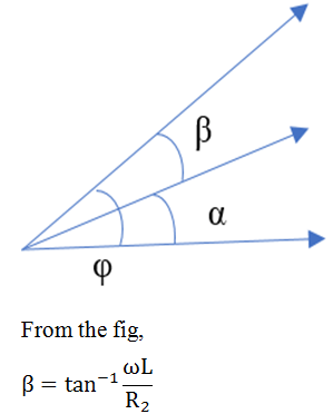
where, R2 = r2 + R = total resistance of the pressure coil
r2 = resistance of pressure coil
R = series resistance with the pressure coil
I1 = load current.
7. Wattmeters are compensated for errors due to inductance by _________
a) using a series capacitor
b) using a parallel capacitor
c) using a series resistance
d) using a parallel resistance
Answer: b
Explanation: Wattmeters are compensated for errors caused by the inductance of pressure coil through the connection of a suitable parallel capacitor with multiplier resistance R.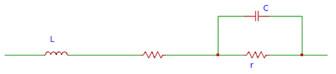
Fig illustrates that the total impedance of the pressure coil circuit Z2 equals the total resistance of the pressure coil circuit namely R2.
8. Eddy currents are induced in solid metal parts within the thickness of the conductor.
a) True
b) False
Answer: a
Explanation: Eddy currents produce their own field. They affect the magnitude and phase of the current flowing through the current coil. This leads to errors. As a result, the wattmeter reads low values for lagging power factors and high values for leading power factors.
9. What is the effect of frequency on the torque of a moving system?
a) torque is half of the frequency
b) torque is twice the frequency
c) torque is thrice the frequency
d) torque is four times the frequency
Answer: b
Explanation: In a wattmeter, the torque of the moving system is affected by the frequency. Torque is twice the natural frequency with respect to the supply voltage. As a result of this, pointer in the measurement scale vibrates causing difficulty in reading.
Low Power Factor Wattmeter
1. In an ordinary dynamometer, the deflecting torque is _________
a) small
b) medium
c) large
d) very large
Answer: a
Explanation: The deflecting torque in an ordinary dynamometer is small. The current and pressure coils are excited. The measurement of power factor is inaccurate.
2. Errors are introduced by ________
a) capacitance
b) inductance
c) resistance
d) impedance
Answer: b
Explanation: At low power factors in an ordinary dynamometer type wattmeter, the errors are caused due to inductance of the pressure coil.
Extension Of Instrument Ranges MCQs
3. Power coil has a low value of ________
a) inductance
b) capacitance
c) resistance
d) impedance
Answer: c
Explanation: In a low power factor dynamometer type wattmeter, the pressure coil is designed in order to have a low value of resistance. The current flowing through the pressure coil is increased in order to raise the operating torque.
4. Resistance of pressure coil in a low power factor dynamometer type wattmeter is ________
a) once time
b) three times
c) hundred times
d) ten times
Answer: d
Explanation: In a low power factor dynamometer type wattmeter, pressure coil has a resistance value that is one tenth of the actual with respect to unity power wattmeters. This is done in order to ensure a reasonable amount of torque at low power factors.
5. Low power factor wattmeters are designed to ________
a) have a low torque
b) have a high torque
c) have a medium torque
d) have no torque
Answer: a
Explanation: Low power factor wattmeters have a low value of control torque. They provide full scale deflection for low values of power factors of the order of 0.1.
6. Power loss in the current coil is ________
a) less
b) more
c) intermediate
d) very less
Answer: b
Explanation: Low power factor circuits have low power. Current coil constitutes a high current. As a result, the power loss in the current coil is high. The reading obtained from the wattmeter is prone to errors.
7. Pressure coil has no error.
a) True
b) False
Answer: b
Explanation: Pressure coil has an error induced due to inductance. It is given by the relation EI sinΦ tanβ. As value of Φ is large for low value of power factor, the error is high in a pressure coil.
8. Error in a pressure coil can be compensated.
a) True
b) False
Answer: a
Explanation: In a low power factor wattmeter, by connecting a capacitor of value C across a portion of the resistance R in the circuit the error in the pressure coil can be compensated.
Induction Type Single Phase Energy Meter
1. Induction type instruments are used for ____________
a) A.C. measurements
b) D.C. measurements
c) Resistance measurements
d) Voltage measurements
Answer: a
Explanation: A.C. measurements are made using Induction type instruments. Induction type energy meter is used to measure the energy that is consumed in A.C. circuits only.
2. Driving system in an induction type single phase energy meter consists of _________
a) one magnet
b) two electromagnets
c) five electromagnets
d) ten magnets
Answer: b
Explanation: In an induction type single phase energy meter, the driving system consists of two electromagnets, namely series electromagnet and shunt electromagnet.
3. Series electromagnet consists of _________
a) L shaped laminations
b) T shaped laminations
c) U shaped laminations
d) Y shaped laminations
Answer: c
Explanation: The driving system of an induction type single phase energy meter consists of U shaped laminations made of silicon steel. The laminations are insulated from one another and pressed to form the core.
4. Shunt magnet consists of _________
a) N shaped laminations
b) E shaped laminations
c) S shaped laminations
d) M shaped laminations
Answer: d
Explanation: The driving system of an induction type single phase energy meter consists of M shaped laminations made of silicon steel. The laminations are insulated from one another and pressed to form the core of the shunt magnet.
5. Shunt magnet has _________
a) large turns of wire
b) small turns of wire
c) medium turns of wire
d) no turns or wires
Answer: a
Explanation: The central limb of the shunt magnet has a large number of turns. It connected across the supply and is known as the voltage coil or potential coil. It is excited using a current value that is proportional to the applied voltage.
6. Moving system of the induction type single phase energy meter has _________
a) heavy aluminium disc
b) light aluminium disc
c) medium aluminium disc
d) no aluminium disc
Answer: b
Explanation: Aluminium disc is provided in the air gap between the series and shunt magnets. Jewel bearings support the spindle. Hence the moving system in an induction type single phase energy meter consists of light aluminium disc.
7. Braking system consists of _________
a) bar magnet
b) temporary magnet
c) permanent magnet
d) super magnet
Answer: c
Explanation: In an induction type single phase energy meter, edge of the aluminium disc consists of a permanent magnet also known as a brake magnet. E.m.f is induced in the aluminium disc when it rotates as a result of the magnetic field produced by the brake magnet.
8. What is the effect of eddy currents in the aluminium disc?
a) varies by a factor of twice the disc length
b) independent of the disc speed
c) varies by a factor of four times the disc size
d) proportional to the disc speed
Answer: d
Explanation: The eddy currents induced in an aluminium disc vary in proportion to the speed of the disc. As a result the braking torque exerted on the disc varies in proportion to the speed.
9. An energy meter produces a flux of ∅ when connected to a supply V.
a) True
b) False
Answer: a
Explanation: Flux ∅ is produced in an energy meter when it is connected to a supply voltage of magnitude V volts. Since the potential coil is highly inductive, current and flux lag the voltage by 90°.
Lag Adjustment Devices
1. The energy meter always measures the load energy correctly.
a) True
b) False
Answer: b
Explanation: When the difference in phase angles between the shunt magnetic flux and the applied voltage is 90 degrees (lagging), the reading of the load energy obtained from an energy meter is correct.
2. Obtaining correct reading from the energy meter requires ______________
a) low resistance and iron losses
b) high resistance and iron losses
c) high resistance and low iron losses
d) low resistance and high iron losses
Answer: a
Explanation: In order to obtain an exact reading for the energy consumed by a load using an energy meter, we require the pressure coil to have a low value of resistance and low iron losses.
3. Phase angle can be made 90 degrees using ____________
a) lead circuit
b) lag circuit
c) special design
d) transformer
Answer: c
Explanation: Phase angle in an energy meter can be made approximately 90 degrees by making use of a special design in the energy meter.
4. Shading coil consists of many thick turns.
a) True
b) False
Answer: b
Explanation: On the central limb of a shunt magnet we can make use of a shading coil. The shading coil consists of a few fairly thick turns. The figure below shows a shading coil on the central limb of the shunt magnet.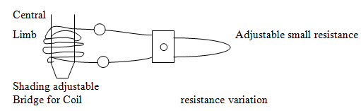
5. Copper shading bands are _________
a) placed as resistance
b) placed as wire
c) placed outside the central limb
d) placed around central limb
Answer: d
Explanation: The central limb of a shunt magnet consists of copper shading bands. They can be moved up or down by making use of the central limb. Figure below illustrates the use of copper shading bands.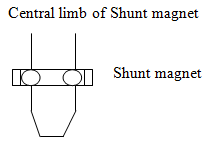
6. As copper shading bands move up ________
a) more flux is induced
b) less flux is induced
c) intermediate flux is induced
d) no flux is induced
Answer: a
Explanation: When the copper shading bands are moved up the central limb, more flux is induced. As a result the difference in angle between the phase and voltage increases. The angle can be made approximately equal to 90 degrees.
7. Shunt flux is made to lag the applied voltage using ________
a) lead circuit
b) lag adjustment
c) lead-lag circuit
d) transformer
Answer: b
Explanation: We make use of shading coil on the central limb of a shunt magnet and shading bands in order to make the shunt flux to lag the applied voltage by almost 90 degrees.
8. At overloads, magnetic shunt ________
a) aids the series flux
b) diverts series flux
c) maintains zero flux
d) disables the shunt flux
Answer: b
Explanation: As the magnetic shunt reaches saturation at overloads, magnetic shunt diverts the flux due to series magnet. As a result a large portion of the flux appears in the gap of the air disc. This compensates the self braking torque.
Friction and Overload Compensation
1. Energy meter reads correctly when the ___________
a) torque is small
b) torque is large
c) torque is medium
d) torque is zero
Answer: a
Explanation: The reading in an energy meter is obtained correctly when the torque value is small at low loads. It is independent of the load on the meter an acts in the same direction as the driving torque.
2. Small torque for energy meter is provided __________
a) by a supply
b) by a shading loop
c) by unshaded loop
d) by a transformer
Answer: b
Explanation: Friction can be compensated in an energy meter by making use of a shading loop. It is placed between the central limb of the shunt magnet and a disc. Figure below illustrates the same.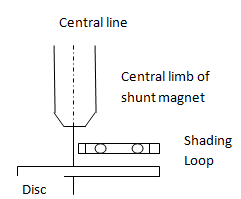
3. Driving torque is small and is adjustable.
a) True
b) False
Answer: a
Explanation: Interaction between the parts of the shaded and unshaded fluxes, obtained through a shading loop leads to a small driving torque. The value of the torque can be adjusted through lateral movement of the loop.
Measurement Of Inductance And Capacitance MCQs
4. Friction torque is eliminated by _________
a) using lubricating oil
b) by suspending the components in air
c) by adjusting the position of limb
d) by using steel alloy components
Answer: c
Explanation: We can eliminate the friction torque completely by adjusting the position of the shading loop. This enables in providing compensation for the frictional torque.
5. Frictional errors are dominant in an energy meter.
a) True
b) False
Answer: a
Explanation: Frictional errors exist in an energy meter at the top as well as bottom surfaces even at low value of loads. Even when the disc is rotating slowly errors due to friction exist in an energy meter.
6. At full load, disc __________
a) partially revolves and then stops
b) continuously revolves
c) does not revolve at all
d) revolves in an alternating fashion
Answer: b
Explanation: When an energy meter is operated in full load condition, disc revolves continuously due to the field of the series magnet. As a result, an e.m.f is induced in the disc.
7. Self braking torque is _________
a) proportional to cube of load current
b) proportional to load current
c) proportional to square of load current
d) proportional to reciprocal of load current
Answer: c
Explanation: In an energy meter, the self braking torque is dependent on the square of the load current. As a result the disc rotates at a slightly slower speed at high value of loads.
8. Self braking action is minimised by _________
a) maintaining high speed for disc
b) maintaining medium speed for disc
c) keeping the disc at rest
d) maintaining low speed for disc
Answer: d
Explanation: In an energy meter we can minimise or eliminate the self braking action by keeping the disc speed as low as possible at full load condition. This is achieved by maintaining the flux due to the current coil smaller than that due to the shunt coil. The figure below shows the compensating device.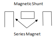
9. Overload compensating devices is _________
a) in the form of a magnetic shunt
b) in the form of a series magnet
c) in the form of a transformer
d) in the form of a supply
Answer: a
Explanation: Magnetic shunt reaches saturation at overloads. As a result, its permeability reduces. Hence the overload compensating device takes the form of a magnetic shunt.
Errors in Single Phase Energy Meters
1. Magnitude of flux in an energy meter varies __________
a) due to abnormal currents and voltages
b) due to high resistance and inductance values
c) due to changes in the transformer turns
d) due to the induced e.m.f in the windings
Answer: a
Explanation: In the driving system of an energy meter, magnitude of flux can be incorrect as a result of abnormal values of currents and voltages. This occurs due to a change in the resistance of the pressure coil circuit.
2. Phase angles in an energy meter cannot be incorrect.
a) True
b) False
Answer: b
Explanation: In an energy meter, phase angle errors occur as a result of improper adjustments of lag condition, abnormal frequencies etc. Due to temperature, changes in resistance values also lead to error in the phase angle.
3. Energy meter creeps __________
a) due to change in supply
b) due to reversal in polarity of voltage
c) due to asymmetry in magnetic circuit
d) due to turns ratio of transformer
Answer: c
Explanation: In an energy meter, when the magnetic circuit is asymmetrical, a driving torque is produced. As a result of this driving torque, the energy meter creeps.
4. Supply voltage in an energy meter is __________
a) constant always
b) zero always
c) depends on the load
d) can fluctuate
Answer: d
Explanation: Generally the supply voltage is constant in an energy meter. It can fluctuate as a result of unavoidable reasons leading to errors in the reading of the energy meter.
5. How is the flux of shunt coil related to voltage?
a) flux is proportional to square of voltage
b) directly proportional
c) inversely proportional
d) independent of each other
Answer: a
Explanation: In an energy meter, the supply voltage may fluctuate as a result of unavoidable reasons leading to errors in the reading. Supply voltage causes the shunt flux to induce an e.m.f in the disc. This is results in a self braking torque proportional to square of the voltage.
6. How can temperature effect be compensated in an energy meter?
a) through heat sinks
b) by a temperature shunt
c) by using resistance
d) by using a coolant
Answer: b
Explanation: The resistance of the copper and aluminium parts in an energy meter increase with an increase in the temperature. As a result the disc rotates with a speed that is higher than actual. Temperature effects can be compensated by making use of a temperature shunt on the brake magnet.
7. Disc rotates slowly in some energy meters.
a) True
b) False
Answer: a
Explanation: Even when there is no current flow through the energy meter, disc rotates slowly. This is known as creeping. This is occurs as a result of the over compensation provided for friction.
8. Creeping is avoided by __________
a) reversing the polarity of the voltage
b) drilling two diametrically opposite holes
c) holding the disc
d) increasing the friction
Answer: b
Explanation: In an energy meter, creeping causes the disc to rotate even when there is no current flowing. By drilling two diametrically opposite holes under the edge of the poles of a shunt magnet, rotation of the disc is limited to a minimum value.
9. In some energy meters, creeping can be avoided by __________
a) attaching small gold pieces
b) attaching small aluminium pieces
c) attaching small iron pieces
d) attaching small zinc pieces
Answer: c
Explanation: By attaching some iron pieces to the edge of the disc, creeping can be limited in some energy meters. Force of attraction that is experienced by the brake magnet as a result of the iron piece is enough to eliminate the creeping.
Electronic Energy Meter, Adjustments in Single Phase Energy meters
1. An electronic energy meter makes use of ___________
a) IC
b) Transformer
c) CRO
d) Multimeter
Answer: a
Explanation: Basically, integrated circuits also known as IC’s are used for the operation of an electronic energy meter.
2. Measurement of energy involves _________
a) inductance and capacitance measurement
b) power consumption and time duration
c) resistance measurement and voltage drop
d) current consumption and voltage drop
Answer: b
Explanation: An electronic energy meter is used in two stages. Energy measurement basically involves the measurement of power and the time duration. In the first stage, it is used as a wattmeter while in the second stage it is used monitoring the power consumed in a time interval.
3. Average power is _________
a) product of voltage and current
b) product of average current and voltage
c) product of instantaneous voltage and current
d) product of absolute voltage and current
Answer: c
Explanation: The average power is computed as the product of the instantaneous voltage across the load and the instantaneous current flowing through the load. A scaling device is used to bring the supply voltage to a proper level.
4. What is the role of a multiplier?
a) it multiplies the voltage and current
b) divides the alternating voltage and current
c) supplies instantaneous voltage and current
d) multiplies alternating voltage and current
Answer: d
Explanation: A multiplier basically performs the multiplication of the alternating voltage and the current. Multiplier also provides the current in the form of instantaneous power to a voltage controlled oscillator.
5. Frequency of oscillation in an electronic energy meter depends on __________
a) output current of multiplier
b) output voltage of multiplier
c) output power of multiplier
d) input resistance of multiplier
Answer: a
Explanation: Oscillator used in an energy meter generates a square wave. The frequency of the this depends on the output current flowing through the multiplier.
6. Analog signal is converted _________
a) into oscillations
b) into digital
c) into pulses
d) into current
Answer: b
Explanation: The analog signal obtained in an electronic energy meter is converted into digital by making use of a digital circuit. By making use of a seven-segment display, energy is mentioned in watt-hours.
7. An electronic energy meter is advantageous compared to conventional ones.
a) True
b) False
Answer: a
Explanation: An electronic energy meter does not have frictional losses, creeping is not needed irrespective of the nature of the load such as low load, full load power factor, etc and the accuracy in the reading is of the order of ±1%.
8. Energy meter can be directly used in measurement.
a) True
b) False
Answer: b
Explanation: Adjustments need to be made in an energy meter before it is used for the measurement of energy. This is done in order to keep the errors due to measurement within allowable limits of ±5 %.
9. Creeping in an energy meter can be found using _________
a) creep adjustment
b) preliminary light load adjustment
c) full load u.p.f adjustment
d) light load adjustment
Answer: b
Explanation: Energy meter can be tested for creeping using preliminary light load adjustment. Disc holes are so positioned that they aren’t under the poles of a series magnet.
10. Preliminary light load adjustment involves _________
a) applying rated voltage across current coil
b) making use of a light load
c) applying rated voltage across pressure coil
d) adjusting the light load
Answer: c
Explanation: Rated voltage is applied across the pressure coil. No current flows through the current coil. Till the disc stops rotating, light load device or equipment is adjusted continuously.
11. Creep adjustment involves _________
a) adjusting the creep
b) exciting the current coil
c) adjusting the turns ratio
d) exciting the pressure coil
Answer: d
Explanation: The pressure coil is excited by 110% with respect to the rated voltage. Load current is zero. The meter will not creep provided the light load is adjusted correctly.
12. Light load adjustment involves _________
a) applying rated voltage across the pressure coil
b) adjusting a light load
c) applying rated current across the transformer
d) applying rated voltage across the current coil
Answer: a
Explanation: Disc rotation is adjusted in such a way that correct speed is maintained. The pressure coil is supplied with the rated voltage and the current coil is provided with only about 5 % of the full load at u.p.f.
13. Low power factor adjustment involves _________
a) adjusting the power factor at lower loads
b) applying rated voltage to pressure coil and a p.f. of 0.5 for current coil
c) only applying rated voltage to pressure coil
d) only a p.f. of 0.5 for the current coil
Answer: b
Explanation: Rated voltage is applied to the pressure coil. The current coil is provided with a current at 0.5 p.f. lagging. Till the disc rotates at correct speed, lag device is adjusted.
14. Full load u.p.f adjustment involves _________
a) adjusting the loads at unity power factor
b) applying rated voltage to pressure coil and a p.f. of unity for current coil
c) only applying rated voltage to pressure coil
d) only a p.f. of unity for the current coil
Answer: c
Explanation: Rated voltage is applied to the pressure coil. The current coil is provided with a current at unity p.f. Errors are kept minimum and the position of the brake magnet is so adjusted that disc rotates at the correct speed.
Phase Sequence Indicator
1. Phase sequence indicator gives the maximum value of phase voltages.
a) True
b) False
Answer: a
Explanation: The phase sequence for a three phase supply indicates the order in which maximum values of phase voltages ER, EY, and EB occur. A three phase supply can be in either RYB or RBY configuration.
2. Synchronization of A.C. supply means __________
a) different phase sequence
b) same phase sequence
c) zero phase
d) using a transformer
Answer: b
Explanation: During synchronization, the phase sequences of any two given supplies are maintained equal. This is ensured by making use of a phase sequence indicator.
Measurement Of Resistance MCQs
3. How many types of phase sequence indicators are there?
a) 1
b) 5
c) 2
d) 10
Answer: c
Explanation: Generally, two types of phase sequence indicators are used. The first one is the rotating type while the second type is the static type. Usually the rotating type of phase sequence indicator is used.
4. A rotating phase sequence indicator consists of ________
a) 1 coil
b) 2 coils
c) 5 coils
d) 3 coils
Answer: d
Explanation: A rotating type of phase sequence indicator basically consists of three coils. These are mounted at 120º to each other is space. The ends of the coils are connected to the terminals R, Y, and B respectively.
5. The three coils are ________
a) star connected
b) delta connected
c) not connected
d) shorted
Answer: a
Explanation: In a rotating type phase sequence indicator, the three coils are connected in the form of a star and excited by a three-phase supply.
6. Excitation of the three coils produces ________
a) a static magnetic field
b) a rotating magnetic field
c) a static electric field
d) a rotating electric field
Answer: b
Explanation: Aluminum disc is mounted on the top of the three coils. A rotating magnetic field is produced when the three coils are excited by a supply of three phase. As a result e.m.f with eddy current effects are induced in the coils.
7. Eddy e.m.f produces a torque.
a) True
b) False
Answer: a
Explanation: A rotating magnetic field is produced when the three coils are excited by a supply of three phase. As a result, eddy e.m.f circulates in the disc. A torque is produced as a result of the interaction between the eddy currents and the rotating magnetic field.
8. Disc rotation is determined by ________
a) the supply voltage
b) an arrow
c) the turns ratio
d) the load current
Answer: b
Explanation: Direction of rotation of the disc is determined by making use of an arrow that is marked on the disc. The phase sequence of the supply voltage is same as that mentioned on the terminals of the meter provided disc rotates in the same direction as the arrow head.
Advanced Problems on Measurement of Power in Polyphase Circuit
1. In the Two wattmeter method of measuring power in a balanced three-phase circuit, one wattmeter shows zero and the other positive maximum. The load power factor is?
a) 0
b) 0.5
c) 0.866
d) 1.0
Answer: b
Explanation: The load power factor is = 0.5. Since at this power factor one wattmeter shows zero and the other shows a positive maximum value of power.
2. Two watt meters, which are connected to measure the total power on a three-phase system supplying a balanced load, read 10.5 kW and – 2.5 kW respectively. What is the total power?
a) 13.0 kW
b) 13.0 kW
c) 8.0 kW
d) 8.0 kW
Answer: d
Explanation: w1 = 10.5 kW
w2 = -2.5 kW
w = w1 + w2 = 8 kW
So, tan ∅ = \(\frac{1.732(w1-w2)}{(w1+w2)}\) = 2.81
Or, ∅ = 70.43
So, cos ∅ = 0.334.
3. Power flowing in 3-phase, 3-wire system is measured by two wattmeter whose readings are 7000 W and -2500 W. if the voltage of the circuit is 400 V, then what will be the value of capacitance introduced in each phase to make one wattmeter reads zero? The frequency is 50 Hz.
a) 500 μF
b) 668.6 μF
c) 1000 μF
d) 748.5 μF
Answer: b
Explanation: P = P1 + P2 = 7000 – 2500 = 4500 W
∴ Power in each phase = 1500 W
Voltage of each phase = 231 V
So, cos∅ = 0.264
∴ Current in each phase = 24.6 A
∴ Z of each phase = 9.39 Ω
∴ R of each phase = 2.48 Ω
Reactance of each phase = 9.056 Ω
For one watt-meter to read zero, power factor should be 0.5
Now, tan∅ = \(\frac{X}{R}\) or, X = 4.29 Ω
∴ Capacitance reactance required = 9.056 – 4.29 = 4.76 Ω
∴ Capacitance C = \(\frac{1}{2π × 50 × 4.76}\) F = 668.6 μF.
4. A single-phase load is connected between R and Y terminals of a 220 V, symmetrical, 3-phase, 4 wire systems with phase sequence RYB. A watt-meter is connected in the system. The watt-meter will read (pf = 0.8 lagging)?
a) – 795 W
b) – 168 W
c) + 597 W
d) + 795 W
Answer: b
Explanation: VRY = 220∠30°
IRY = \(\frac{220∠30°}{100∠36.86°}\) = 2.2∠-6.68° A
Power = VBN IRY = cos∅ = \(\frac{220}{(3)^{0.5}}\) × 2.2 cos (126.86°)
= -167.6 W ≈ – 168 W.
5. The two-wattmeter method is used to measure active power. The system is a 3-phase, 3- wire system. Then, the power reading is?
a) Affected by both negative sequence and zero sequence voltages
b) Affected by negative sequence voltages but not by zero sequence voltages
c) Affected by zero sequence voltages but not by negative sequence voltages
d) Not affected by negative or zero sequence voltages
Answer: d
Explanation: If the phase voltage is unbalanced, then the power reading is not affected by both negative as well as zero sequence voltages. This is a characteristic property of the 2 watt-meter meter since it measures the active power on a three phase three wire system.
6. The ratio of the reading of 2 watt-meters connected to measure power in a balanced 3-phase load is 2: 1 and the load is inductive. The power factor of load is?
a) 0.866 lag
b) 0.615 lead
c) 0.866 lead
d) 0.625 lag
Answer: a
Explanation: Power factor, cosθ = cos arc tan (3)0.5 \(\frac{W_1-W_2}{W_1+W_2}\)
Since, \(\frac{W_1}{W_2} = \frac{2}{1}\)
So, power factor = cos arc tan (3)0.5 \(\frac{2-1}{2+1}\)
= cos 30° = 0.866 lag.
7. Choose the correct statement regarding two watt-meter method for power measurements in 3-phase circuit.
a) When power factor is unity, one of the wattmeters reads zero
b) When the readings of the two watt-meters are equal but opposite sign, the power factor is zero
c) Power can be measured using two watt-meter method only for star connected 3-phase circuit
d) When two watt-meters show identical readings, the power factor is 0.5
Answer: b
Explanation: When power factor is 0, we have ∅ = 90°
P1 = (3)0.5 VIcos (30° – ∅) = (3)0.5 VIcos (30° – 90°) = \(\frac{(3)^{0.5}}{2}\) × VI
P2 = (3)0.5 VIcos (30° + ∅) = (3)0.5 VIcos (30° + 90°) = \(– \frac{(3)^{0.5}}{2}\) × VI
∴Total power P = 0
So, with zero power factor the readings of the two watt-meters are equal but of opposite sign.
8. The meter constant of a single-phase, 230 V induction watt-meter is 600 rev/kW-h. The speed of the meter disc for a current of 15 A at 0.8 power factor lagging will be?
a) 30.3 rpm
b) 25.02 rpm
c) 27.6 rpm
d) 33.1 rpm
Answer: c
Explanation: Meter constant = \(\frac{Number \,of\, revolution}{Energy} = \frac{600 × 230 × 15 × 0.8}{1000}\) = 1656
∴ Speed in rpm = \(\frac{1656}{60}\) = 27.6 rpm.
9. In the measurement of 3-phase power by 2 watt-meter method, if the 2 watt-meter readings are equal, the power factor of the circuit is?
a) 0.8 lagging
b) 0.8 leading
c) Zero
d) Unity
Answer: d
Explanation: Power factor, cosθ = cos arc tan (3)0.5 \(\frac{W_1-W_2}{W_1+W_2}\)
W1 = W2 = cos 0° = 1.
10. The figure shows a three-phase, delta connected load supplied from a 220 V, 50 Hz, 3-phase balanced source. The pressure Coil (PC) and Current Coil (CC) of a watt-meter are connected to the load as shown, with the coil polarities suitably selected to ensure a positive deflection. The watt-meter reading will be?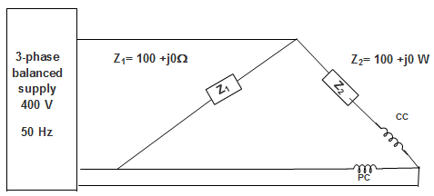
a) Zero
b) 1600 W
c) 242 W
d) 400 W
Answer: c
Explanation: Watt-meter reading = Current through CC × Voltage across PC × cos (phase angle).
IBR = ICC = \(\frac{220∠120°}{100°}\) = 2.2∠120°
VYB = VPC = 220∠-120°
w = 2.2∠120°× 220∠-120° × cos 240° = 242 W.
Advanced Miscellaneous Problems on Measurement of Power
1. A coil (which can be modelled as a series RL circuit) has been designed for high Q performance. The voltage is rated at and a specified frequency. If the frequency of operation is increased 10 times and the coil is operated at the same rated voltage. The new value of Q factor and the active power P will be?
a) P is doubled and Q is halved
b) P is halved and Q is doubled
c) P remains constant and Q is doubled
d) P decreases 100 times and Q is increased 10 times
Answer: d
Explanation: ω2 L = 10 ω1 LR will remain constant
∴ Q2 = \(\frac{10 ω_1 L}{R}\) = 10 Q1
That is Q is increased 10 times.
Now, I1 = \(\frac{V}{ω_1 L}\)
For a high Q coil, ωL ≫> R,
I2 = \(\frac{V}{10 ω_1 L} = \frac{I_1}{10}\)
∴ P2 = \(R (\frac{I_1}{10})^2 = \frac{P_1}{100}\)
Thus, P decreases 100 times and Q is increased 10 times.
2. Two watt-meters, which are connected to measure the total power on a three-phase system supplying a balanced load, read 20.5 kW and -3.5 kW respectively. The total power is?
a) 13.0 kW
b) 17 kW
c) 15 kW
d) 19 kW
Answer: d
Explanation: w1 = 20.5 kW, w2 = -3.5 kW
∴ w = w1 + w2 = 20.5 – 3.5 = 17 kW.
3. A circuit is used to measure the power consumed by the load. The current coil and the voltage coil of the watt-meter have 0.02 Ω and 1000 Ω resistances respectively. The measured power (as compared to the load power) will be?
a) 0.4 % less
b) 0.2 % less
c) 0.2 % more
d) 0.4 % more
Answer: c
Explanation: Power indicated by watt-meter = 400 × 20 + 202 × 0.02 = 4008 W
Percentage increase = \(\frac{4008-4000}{4000}\) × 100 = 0.2 % more.
4. A sampling watt-meter is used to measure the average power of a load. The peak to peak voltage of the square wave is 10 V and the current is a triangular wave of 5A p-p. The reading in watt will be?
a) Zero
b) 25 W
c) 50 W
d) 100 W
Answer: a
Explanation: If we consider both the waves, we can see positive power and negative power in each case are equal. So, the net resultant power is zero.
5. The line to line input voltage to the 3-phase, 50 Hz, AC circuit, is 100 V rms. Assuming that the phase sequence is RYB; the watt-meters would read?
a) W1 = 886 W and W2 = 886 W
b) W1 = 500 W and W2 = 500 W
c) W1 = 0 W and W2 = 1000 W
d) W1 = 250 W and W2 = 750 W
Answer: c
Explanation: W1 = 100 × 20 cos 90° = 0
W2 = \(\frac{100 × 20 × \sqrt{3}}{\sqrt{3} × 2}\) = 1000 W.
6. The meter constant of a single-phase, 100 V induction watt-meter is 600 rev/kW-h. The speed of the meter disc for a current of 15 A at 0.8 power factor lagging will be?
a) 30.3 rpm
b) 16 rpm
c) 12 rpm
d) 33.1 rpm
Answer: c
Explanation: Meter constant = \(\frac{Number \,of\, revolution}{Energy}\)
Number of revolution = \(\frac{600 × 100 × 15 × 0.8}{1000}\) = 720
∴ Speed in rpm = \(\frac{720}{60}\) = 12 rpm.
7. A 3-phase, 600 V motor, the load having 0.6 power factor uses two watt-meter to measure the power. If the power measured be 45 kW, then the reading of each instrument will be?
a) P1 = 35 kW, P2 = 10 kW
b) P1 = 47.25 kW, P2 = -2.25 kW
c) P1 = 39.82 kW, P2 = 5.179 kW
d) P1 = 45 kW, P2 = 0 kW
Answer: c
Explanation: P1 + P2 = 45 kW
And, cos ∅ = 0.6
∴ tan ∅ = 1.33
Or, 1.33 = \(\sqrt{3} \frac{P_1 – P_2}{45} \)
∴ P1 – P2 = 34.64 kW
∴ P1 = 39.82 kW
P2 = 5.179 kW.
8. An average-reading digital Multimeter reads 10 V when fed with a triangular wave, symmetric about the time-axis. If the input is same, the rms reading meter will read?
a) 20/\(\sqrt{3}\)
b) -10/\(\sqrt{3}\)
c) -20/\(\sqrt{3}\)
d) 10/\(\sqrt{3}\)
Answer: d
Explanation: For triangular wave- Average value = \(\frac{V_m}{3}\), rms value = \(\frac{V_m}{\sqrt{3}}\)
\(\frac{V_m}{3}\) = 10 V or, Vm = 30 V
So, rms = \(\frac{30}{\sqrt{3}}\) = 10\(\sqrt{3}\).
9. In the Two wattmeter method of measuring power in a balanced three-phase circuit, one wattmeter shows zero and the other positive maximum. The load power factor is?
a) 0
b) 0.5
c) 0.866
d) 1.0
Answer: b
Explanation: The load power factor is = 0.5. Since at this power factor one wattmeter shows zero and the other shows a positive maximum value of power.
10. Two watt-meters connected to measure the total power on a three-phase system supplying a balanced load reads 10.5 kW and -2.5 kW respectively. Then the total power factor is?
a) 0.334
b) 0.684
c) 0.52
d) 0.334
Answer: d
Explanation: w1 = 10.5 kW, w2 = -2.5 kW
∴ w = w1 + w2 = 8 kW
Also, tan ∅ = 2.81
∴ ∅ = 70.43° or, cos ∅ = 0.3347.