Latest Measurement of Resistance ( Electrical Measurements ) MCQs – Electrical Measurements MCQs

Latest Electrical Measurements MCQs
By practicing these MCQs of Measurement of Resistance ( Electrical Measurements ) MCQs – Latest Competitive MCQs , an individual for exams performs better than before. This post comprising of objective questions and answers related to “ Measurement of Resistance ( Electrical Measurements ) Mcqs “. As wise people believe “Perfect Practice make a Man Perfect”. It is therefore practice these mcqs of Electrical Measurements to approach the success. Tab this page to check ” Measurement of Resistance ( Electrical Measurements )” for the preparation of competitive mcqs, FPSC mcqs, PPSC mcqs, SPSC mcqs, KPPSC mcqs, AJKPSC mcqs, BPSC mcqs, NTS mcqs, PTS mcqs, OTS mcqs, Atomic Energy mcqs, Pak Army mcqs, Pak Navy mcqs, CTS mcqs, ETEA mcqs and others.
Electrical Measurements MCQs – Measurement of Resistance ( Electrical Measurements ) MCQs
The most occurred mcqs of Measurement of Resistance ( ) in past papers. Past papers of Measurement of Resistance ( Electrical Measurements ) Mcqs. Past papers of Measurement of Resistance ( Electrical Measurements ) Mcqs . Mcqs are the necessary part of any competitive / job related exams. The Mcqs having specific numbers in any written test. It is therefore everyone have to learn / remember the related Measurement of Resistance ( Electrical Measurements ) Mcqs. The Important series of Measurement of Resistance ( Electrical Measurements ) Mcqs are given below:
Kelvin Bridge
1. Kelvin’s bridge consists of _________
a) double bridge
b) single bridge
c) half bridge
d) three fourth bridge
Answer: a
Explanation: Kelvin’s bridge consists of two additional arms compared to a Wheatstone bridge. Hence it is also known as a double bridge.
2. The range of resistance measured in a Kelvin bridge is _________
a) 10Ω to 10 mΩ
b) 1Ω to 10 μΩ
c) 0.01Ω to 10 MΩ
d) 0.1Ω to 10 nΩ
Answer: b
Explanation: Kelvin bridge is used for the measurement of low resistances. Low resistances vary in the range of 1Ω to 10 μΩ.
3. Accuracy of Kelvin bridge is of the order of _________
a) ±0.5 to ±2 %
b) ±0.05 to ±0.02 %
c) ±0.05 to ±0.2 %
d) ±0.005 to ±0.02 %
Answer: c
Explanation: As Kelvin bridge is used for the measurement of low resistance values, the accuracy of measurement of low resistances in a Kelvin bridge is of the order of ±0.05 to ±0.2 %.
4. What is the balance equation of Kelvin bridge?
a) Rx = R2R3R1
b) Rx = R1R2R3
c) Rx = R1R2
d) Rx = R1R3R2
Answer: d
Explanation: The balance equation in a Kelvin bridge is given by the relation Rx = R1R3R2
where,
R1, R2, R3, and Rx form the ratio arms
Rx is the value of the unknown resistance.
5. What is the effect of load and contact resistance in Kelvin bridge?
a) independent
b) fully dependent
c) partially dependent
d) depends on the resistance value
Answer: a
Explanation: Effect of contact and lead resistances are completely eliminated in a Kelvin bridge as they don’t appear in the balance equation. Hence the Kelvin bridge is independent of the load and contact resistances.
6. The relation between ratio of resistance arms and ratio of resistance arms of second bridge is _________
a) unequal
b) equal
c) twice
d) one forth
Answer: b
Explanation: The relation between the ratio of the resistances of resistance arm and second resistance arm is equal for balance condition.
7. Why Kelvin bridge is used for measurement of low resistance?
a) due to e.m.f source used
b) due to a large current flow
c) due to contact and lead resistance
d) due to power dissipation across the circuit
Answer: c
Explanation: While measuring very low resistances the contact and lead resistances cause significant errors in the value of the measured resistance. As a result Kelvin bridge is used for measurement of low resistances.
8. What is the condition to achieve a high sensitivity in a Kelvin bridge?
a) low voltage
b) high power
c) medium resistance
d) high current
Answer: d
Explanation: The condition to achieve a high sensitivity in a Kelvin bridge is that the measuring current should be high enough so as to sensitize the null detector.
9. Kelvin bridge can be calibrated to read _________
a) inductance and Quality factor value
b) capacitance only
c) power and voltage
d) current and frequency
Answer: a
Explanation: In its basic form a Kelvin bridge is used for the measurement of low resistance. A Kelvin bridge can be used for the measurement of inductance and Quality factor value through calibration.
10. Why can’t a Kelvin bridge be used for the measurement of low Quality factor value?
a) due to thermoelectric effect
b) due to balance problem
c) due to the dull detector used
d) due to temperature
Answer: b
Explanation: A Kelvin bridge can be used for the measurement of high Quality factor values. Due to bridge imbalance problem, Kelvin bridge can’t be used for measuring low Quality factor values.
Megger
1. High resistances are of the order of __________
a) 0.1 Mῼ
b) 10 mῼ
c) 1 kῼ
d) 10 Gῼ
Answer: a
Explanation: Resistances of the order of 0.1 Mῼ and above are known as high resistances. Resistance values upto 1 ῼ are known as low resistances. Resistances upto a few kῼ are known as medium resistances.
2. Megger is a ________
a) source of e.m.f
b) source to measure high resistance
c) type of a null detector
d) current carrier
Answer: b
Explanation: Megger is a portable instrument Answer: d
Explanation: Ohm’s law is applicable to only purely resistive circuits which are based on the linearity principle. Megger basically works on the principle of electromagnetic induction.o measure high resistances.
3. Megger is also used for ________
a) providing additional e.m.f
b) bridge balance
c) testing insulation resistance
d) controlling the temperature
Answer: c
Explanation: A null detector is used to balance the bridge. Additional e.m.f can be provided to a circuit by increasing the magnitude of the voltage source. Megger is used for testing the insulation resistance of cables.
4. Megger works on the principle of ________
a) kirchhoff’s current laws
b) ohm’s law
c) gauss’s law
d) electromagnetic induction
Answer: d
Explanation: Ohm’s law is applicable to only purely resistive circuits which are based on the linearity principle. Megger basically works on the principle of electromagnetic induction.
5. The role of the permanent magnet in a megger is to ________
a) provide field
b) provide voltage
c) generate power
d) balance the circuit
Answer: a
Explanation: Voltage can be provided by means of an e.m.f source. Power generation occurs when current flows through a circuit. Permanent magnet in a megger is used to provide a field for the generator as well as the ohmmeter.
6. A guard ring is provided in a megger to ________
a) protect the circuit
b) eliminate error
c) reduce current flow
d) limit the temperature rise
Answer: b
Explanation: Temperature rise can be prevented by reducing the flow of excessive current through the circuit. The role of a guard ring in a megger is to reduce the errors due to leakage current.
7. The supply to the megger is given by ________
a) ac motor
b) ac generator
c) permanent magnet dc motor
d) dc generator
Answer: c
Explanation: Megger works on the principle of electromagnetic induction. Supply can be given through a dc motor. A permanent magnet dc motor driven by hand is used as a source of supply to the megger.
8. The moving element of the ohmmeter in a megger consists of ________
a) 1 coil
b) 4 coils
c) 3 coils
d) 10 coils
Answer: c
Explanation: The moving element of an ohmmeter in a megger consists of three coils, namely current or deflection coil, pressure or control coil and compensating coil.
9. The role of the compensating coil in a megger is ________
a) reduce current
b) increase voltage
c) control temperature
d) scaling
Answer: d
Explanation: Temperature is controlled by minimising the flow of current through the circuit. Better scaling proportions can be achieved in a megger by making use of a compensating coil.
Applications of Megger
1. Why is the scale of a megger calibrated in megaohms?
a) to indicate resistance
b) to minimise the current flow
c) to increase the voltage drop
d) to reduce the temperature
Answer: a
Explanation: Current flow through the circuit depends on the magnitude of the e.m.f source. In order to indicate the resistance value indicated by the pointer, the scale of a megger is calibrated.
2. Megger can be used for verifying the electrical insulation level of ____________
a) passive components such as resistance, capacitor and inductance
b) devices such as motor, cable, etc
c) solid state devices
d) liquid crystal devices
Answer: b
Explanation: Solid state devices consist of power electronic components and drives. One of the applications of a Megger circuit is in verifying the electrical insulation levels of devices such as motor, cable, generator, etc.
3. Continuity between any two points can be measured using _________
a) ammeter
b) voltmeter
c) megger
d) galvanometer
Answer: c
Explanation: A galvanometer is used for detecting the balance condition in a bridge circuit. An ammeter measures the current flow through the circuit while the voltmeter is used for determining the voltage across the bridge circuit. A megger circuit can be used to determine the continuity between any two points.
4. Electrical continuity between any two points exists if _________
a) there is current flow through them
b) there is a wire connecting the points
c) there is sufficient voltage drop
d) pointer shows deflection
Answer: d
Explanation: Voltage drop across the circuit is measured by using a voltmeter. When the pointer displays full deflection, then there is an electrical continuity between the two points.
5. Megger is also known as _________
a) megohmmeter
b) multimeter
c) galvanometer
d) ammeter
Answer: a
Explanation: A galvanometer is used to detect the balance condition. A multimeter can be used for measurement of voltage, current, resistance and power. A megger is also known as a megohmmeter as it is used for the measurement of resistances in the order of Mῼ.
6. The application of a megger is _________
a) to measure resistance
b) to test for leakage
c) to limit the current
d) to increase the emf of the circuit
Answer: b
Explanation: Current flow through a circuit depends on the magnitude of the voltage source. Magnitude of the voltage source can be increased. A megger is mainly used for testing electrical leakages in wires.
7. What is the significance of a megger with respect to high resistance?
a) it is used to limit the current
b) it is used to provide stability
c) used for measuring high resistance with respect to ground
d) it is used for temperature protection
Answer: c
Explanation: Temperature protection can be provided to a bridge circuit by making use of heat sinks. Megger is used for determining very high resistances between the conducting part of a circuit and ground.
8. How is the megger calibrated?
a) in steps of 1 unit per division
b) based on the value of resistance to be measured
c) directly calibrated on the position of the pointer
d) reversely calibrated based on the pointer position
Answer: d
Explanation: The scale in a megger is calibrated such that normal position of a pointer indicates infinity while full scale corresponds to zero resistance.
Measurement of Earth Resistance
1. What is earthing?
a) connecting electrical machines to earth
b) providing a connection to the ground
c) connecting the electrical machines to source
d) providing a source of current
Answer: a
Explanation: Connecting electrical machines to the general mass of the earth by making use of a conducting material with very low resistance is known as earthing.
2. What is an earth electrode?
a) electrode that is connected to earth
b) material used for earthing
c) electrode connected to the circuit
d) electrode which is connected to the mains
Answer: b
Explanation: Electrode connected to the main is basically a source of e.m.f. Conducting material that is used for connecting electrical machinery to the earth is known as an earth electrode.
3. Earth electrode provides ____________
a) high resistance
b) medium resistance
c) low resistance
d) very high resistance
Answer: c
Explanation: In the case of occurrence of any leakage currents due to poor shielding of the apparatus, the earth electrode is used to provide a very low resistance path from the electrical appliances to the earth.
4. How is the condition of an earth electrode measured?
a) by measuring the voltage
b) by measuring the current
c) by measuring the power
d) by measuring resistance
Answer: d
Explanation: The resistance of the earth electrode is measured in order to check whether it is in a good condition or not.
5. In a three phase system, the neutral is _________
a) earthed
b) connected to low voltage
c) connected to high voltage
d) not connected
Answer: a
Explanation: Earthing can be used to maintain a constant line voltage in a three phase system. This is achieved by earthing the neutral.
6. Earthing is used as return conductor in telephone lines and for traction work.
a) True
b) False
Answer: a
Explanation: The complications involved in laying separate telephone cables and the cast used for traction work is minimised. As a result earthing is used as a return conductor in telephone lines and for traction work.
7. Earthing does not help in protecting the equipment.
a) True
b) False
Answer: b
Explanation: Spike voltages occurring as a result of lightning or any other fault can be dissipated to ground by earthing, thus protecting the equipment.
Measurement Of Resistance MCQs
8. After earthing, the different parts of an electrical machinery are at _________
a) infinite potential
b) intermediate potential
c) zero potential
d) undefined potential
Answer: c
Explanation: After earthing, the various parts of electrical machinery such as casing, armoring of cables, etc are at zero potential.
9. Connection of the various parts of a circuit to earth has a _________
a) medium resistance
b) high resistance
c) very high resistance
d) very low resistance
Answer: d
Explanation: Once an electrical apparatus is grounded, most of its components are at ground potential. When the different parts of electrical machinery are connected to the ground, they possess very low resistance.
10. Specific resistance of soil is _________
a) changes from soil to soil
b) is constant
c) depends on the circuit connected to it
d) depends on the supply voltage
Answer: a
Explanation: Specific resistance depends on the nature and properties of a material. Specific resistance is different for various types of soils such as dry soil, rocky soil, wet soil, etc.
Advanced Problems on Measurement of Low Medium and High Resistance
1. Circuit shows the method of Measurement of low resistance by Ammeter-Voltmeter method. The measured resistance Rm for the given Circuit is _________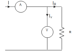
a) Rx + Rv
b) \(\frac{R_x^2}{R_x + R_v}\)
c) \(\frac{R_v^2}{R_x + R_v}\)
d) \(\frac{R_x R_v}{R_x + R_v}\)
Answer: d
Explanation: Measured resistance Rm = \frac{V_x}{I_A} = \frac{V_x}{I_v + I_R}
\frac{I_v}{V_x} = \frac{1}{R_v} And \frac{I_R}{V_x} = \frac{1}{R_X}
So, Rm = \frac{R_x R_v}{R_x+R_v}.
2. Circuit shows the method of Measurement of low resistance by Ammeter-Voltmeter method. What is the percentage error?
a) Zero
b) \frac{R_x}{R_x + R_v} × 100
c) – \frac{R_x}{R_x + R_v} × 100
d) – \frac{R_v}{R_x + R_v} × 100
Answer: c
Explanation: Percentage Error = \frac{R_m – R_x}{R_x} × 100
= \frac{R_x R_v – R_x(R_x-R_v)}{R_x (R_x+R_v)} × 100
∴ Percentage Error = – \frac{R_x}{R_x + R_v} × 100.
3. The readings of polar type potentiometer are I = 12.4∠27.5°, V = 31.5∠38.4°. Then, reactance of the coil will be ________
a) 2.51 Ω
b) 2.56 Ω
c) 2.54 Ω
d) 2.59 Ω
Answer: c
Explanation: Here, V = 31.5∠38.4°
I = 12.4∠27.5°
Z = \frac{31.5∠38.4°}{12.4∠27.5°} = 2.54∠10.9°
But Z = R + jX = 2.49 + j0.48
∴ Reactance X= 2.54 Ω.
4. The voltage drop across a standard resistor of 0.2 Ω is balanced at 83 cm. Find the magnitude of the current, if the standard cell emf of 1.53 V is balanced at 42 m.
a) 13.04 A
b) 10 A
c) 14.95 A
d) 12.56 A
Answer: c
Explanation: Voltage drop per unit length = 1.5342 = 0.036 V/cm
Voltage drop across 83 cm length = 0.036 × 83 = 2.99 V
∴ Current through resistor, I = 2.990.2 = 14.95 A.
5. A resistance R is measured using the connection shown in the below figure.
The current measured is 10 A on ranges 100A and the voltage measured is 125 V on 150 V range. The scales of the ammeter and voltmeter are uniform. The total number of scale divisions of the ammeter is 100 and that of the voltmeter is 150. The scale division can be distinguished. The constructional error of the ammeter is ± 0.3% and that of voltmeter±0.4%. The resistance of the ammeter is 0.25 Ω.
The value of R is?
a) 12.75 Ω
b) 12.0 Ω
c) 12.25 Ω
d) 12.5 Ω
Answer: c
Explanation: Percentage error in ammeter = ±110×100×100 = ± 0.1%
Percentage error in voltmeter= ±110×150×100 = ± 0.067%
So, δI = ± 0.3 ± 0.1 = ± 0.4%
δV = ± 0.4 ± 0.067 = ± 0.467%
R = VI
So, error = ± δV ± δI = ± 0.867
Measured value of resistance = Rm=12510 = 12.5
∴ True value = Rm(1−RaRm) = 12.25 Ω.
6. A resistance R is measured using the connection shown in the below figure.
The current measured is 10 A on ranges 100A and the voltage measured is 125 V on 150 V range. The scales of the ammeter and voltmeter are uniform. The total number of scale divisions of the ammeter is 100 and that of the voltmeter is 150. The scale division can be distinguished. The constructional error of the ammeter is ± 0.3% and that of voltmeter±0.4%. The resistance of the ammeter is 0.25 Ω.
The possible error in the measurement of R is?
a) ±0.11 Ω
b) ±0.15 Ω
c) ±0.867 Ω
d) ±0.625 Ω
Answer: a
Explanation: Possible error is ± 0.867, so,
12.25 ± 0.867%
Or, 12.25 ± 0.11 Ω.
7. Low resistance is measured by ___________
a) De-Sauty’s bridge
b) Maxwell’s bridge
c) Kelvin double bridge
d) Wein’s bridge
Answer: c
Explanation: De-Sauty’s bridge is used for measurement of Capacitance; Maxwell’s bridge is used for measurement of Inductance and Wein Bridge for Frequency. Kelvin double bridge is used for measurement of Low resistance.
8. The resistance can be measured most accurately by _________
a) Voltmeter-Ammeter method
b) Bridge method
c) Multimeter
d) Megger
Answer: b
Explanation: Bridge method applies the concept of null point or bridge balance condition. Multimeter and Megger are used for measuring very high resistances and Voltmeter-Ammeter method is used for Low resistances. A null type instrument has higher accuracy as compared to a deflection type instrument.
9. A slide wire potentiometer has 10 wires of 2 m each. With the help of a standard voltage source of 1.045 V, it is standardized by keeping the jockey at 104.5 cm. If the resistance of potentiometer wires is 2000 Ω, then the value of working current is?
a) 1 mA
b) 10 mA
c) 0.1 mA
d) 0.5 mA
Answer: b
Explanation: Total length of the slide wire = 10 × 200
Total resistance of slide wire = 2000 Ω
∴ Resistance per cm = 1 Ω
Resistance of 104.5 cm = 104.5 Ω
This corresponds to a voltage of 1.045 V
∴ Current = 1.045104.5 = 10 mA.
10. Which of the following method is used for the measurement of Medium Resistance?
a) Kelvin’s double bridge method
b) Carey-Foster bridge method
c) Anderson Bridge
d) Direct-Deflection method
Answer: b
Explanation: Kelvin’s double bridge method is used for measurement of Low Resistance, Anderson Bridge is not used for measurement of Resistance and Direct-Deflection method is used for Measurement of High Resistance.
11. In the Wheatstone bridge shown below, if the resistance in each arm is increased by 0.05%, then the value of Vout will be ________
a) 50 mV
b) Zero
c) 5mV
d) 0.1mV
Answer: b
Explanation: In Wheatstone bridge, balance condition is
R1R3 = R2R4
Here, R1 = 5, R2 = 10, R3 = 16, R4 = 8
And when the Wheatstone bridge is balanced then, at Vout voltage will be Zero.
Advanced Problems on Error Analysis in Electrical Instruments
1. A resistor of 10 kΩ with the tolerance of 5% is connected in parallel with 5 kΩ resistors of 10% tolerance. What is the tolerance limit for a parallel network?
a) 9%
b) 12.4%
c) 8.33%
d) 7.87%
Answer: c
Explanation: Here, R1 and R2 are in parallel.
Then, 1R=1R1+1R2
Or, R = 5015 kΩ
∴△RR=△R1R21+△R2R22
And △R1 = 0.5×10³, △R2 = 0.5×10³
∴△RR=10×1033×10×103×0.5×10310×103+103×1035×103×0.5×1035×103
= 0.530+115=2.530 = 8.33%.
2. A 0-400V voltmeter has a guaranteed accuracy of 1% of full scale reading. The voltage measured by this instrument is 250 V. Calculate the limiting error in percentage.
a) 4%
b) 2%
c) 2.5%
d) 1%
Answer: a
Explanation: The magnitude of limiting error of the instrument
ρA = 0.01 × 400 = 4 V
The magnitude of voltage being measured = 250 V
The relative at this voltage Er = 4250 = 0.016
∴ Voltage measured is between the limits
Aa = As(1± Er)
= 250(1 ± 0.016)
= 250 ± 4 V.
3. The current flowing in a resistor of 1Ω is measured to be 25 A. But it was discovered that ammeter reading was low by 1% and resistance was marked high by 0.5%. Find true power as a percentage of the original power.
a) 95%
b) 101.5%
c) 100.1%
d) 102.4%
Answer: b
Explanation: True current = 25(1 + 0.01) = 25.25 A
True resistance R = 1(1 – 0.005) = 0.995Ω
∴ True power = I2R = 634.37 W
Measured power = (25)2 × 1 = 625 W
∴ TruepowerMeasuredpower × 100 = 634.37625 × 100 = 101.5%.
4. A resistor of 10 kΩ with the tolerance of 5% is connected in series with 5 kΩ resistors of 10% tolerance. What is the tolerance limit for a series network?
a) 9%
b) 12.04%
c) 8.67%
d) 6.67%
Answer: d
Explanation: Error in 10 kΩ resistance = 10 × 5100 = 0.5 kΩ
Error in 5 kΩ resistance = 5 × 10100 = 5 kΩ
Total measurement resistance = 10 + 0.5 + 5 + 0.5 = 16 kΩ
Original resistance = 10 + 5 = 15 kΩ
Error = 16−1515 × 100 = 115 × 100 = 6.67%.
5. Two resistances 100 ± 5Ω and 150 ± 15Ω are connected in series. If the error is specified as standard deviations, the resultant error will be _________
a) ±10 Ω
b) ±10.6 Ω
c) ±15.8 Ω
d) ±20 Ω
Answer: c
Explanation: Given, R1 = 100 ± 5 Ω
R2 = 150 ± 15 Ω
Now, R = R1 + R2
The probable errors in this case, R = ±(R21+R22)0.5 = ± 15.8 Ω.
6. Resistances R1 and R2 have respectively, nominal values of 10Ω and 5Ω and limiting error of ± 5% and ± 10%. The percentage limiting error for the series combination of R1 and R2 is?
a) 6.67%
b) 5.5%
c) 7.77%
d) 2.8%
Answer: a
Explanation: R1 = 10 ± 5%
R2 = 5 ± 10%
R1 = 10 ± 5100 × 10 = 10 ± 0.5Ω
R2 = 5 ± 5100 × 5 = 5 ± 0.5Ω
The limiting value of resultant resistance = 15 ± 1
Percentage limiting error of series combination of resistance = 115 × 100 = 6.67%.
7. A voltmeter has a sensitivity of 1000 Ω/V reads 200 V on its 300 V scale. When connected across an unknown resistor in series with a millimeter. When the milliammeter reads 10 mA. The apparent resistance of the unknown resistor will be?
a) 20 kΩ
b) 21.43 kΩ
c) 18.57 kΩ
d) 22.36 kΩ
Answer: a
Explanation: RT = VTIT
VT = 200 V, IT = 10 A
So, 20 kΩ.
8. A voltmeter has a sensitivity of 1000 Ω/V reads 200 V on its 300 V scale. When connected across an unknown resistor in series with a millimeter. When the milliammeter reads 10 mA. The actual resistance of the unknown resistor will be?
a) 20 kΩ
b) 18.57 kΩ
c) 21.43 kΩ
d) 22.76 kΩ
Answer: c
Explanation: Resistance of voltmeter,
RV = 1000 × 300 = 300 kΩ
The Voltmeter is in parallel with an unknown resistor,
RX = RTRVRT–RV=20×300280 = 21.43 kΩ.
9. A voltmeter has a sensitivity of 1000 Ω/V reads 200 V on its 300 V scale. When connected across an unknown resistor in series with a millimeter. When the milliammeter reads 10 mA. The error due to the loading effect of the voltmeter is ________
a) 3.33%
b) 6.67%
c) 13.34%
d) 13.67%
Answer: b
Explanation: RT = VTIT
VT = 200 V, IT = 10 A
So, RT = 20 kΩ
Resistance of voltmeter,
RV = 1000 × 300 = 300 kΩ
Voltmeter is in parallel with unknown resistor,
RX = RTRVRT–RV=20×300280 = 21.43 kΩ
Percentage error = Actual−ApparentActual × 100
= 21.43−2021.43 × 100 = 6.67%.
10. A 500 A, 50 Hz current transformer has a bar primary. The secondary burden is a pure resistance of 1 Ω and it draws a current of 5 A. If the magnetic core requires 250 Ampere-turn for magnetization, the percentage ratio error is __________
a) 10.56%
b) -10.56%
c) 11.80%
d) -11.80%
Answer: b
Explanation: IM = 250/I = 250 A
Ip Or, R = V2R
∴ R = ± (2 × 1.5 + 5) = ± 8%.
Advanced Miscellaneous Problems on Measurement of Resistance
1. Ra and Rd are the opposite arms of a Wheatstone bridge as are Rc and Rb. The source voltage is applied across Ra and Rc. Then when the bridge is balanced which one of the following is true?
a) Ra = Rc Rd/Rb
b) Ra = Rb Rc/Rd
c) Ra = Rb Rd/Rc
d) Ra = Rb + Rc + Rd
Answer: b
Explanation: At balance condition, Potential at B = Potential at D
∴ VA – Ia Ra = VA – Ib Rb
Or, IaIb=RbRa
Similarly, IaIb=RdRc
∴ Ra = RbRcRd.
2. A setup is used to measure resistance R. The ammeter and voltmeter resistance are 0.01 Ω and 2000 Ω respectively. Their readings are 2 A and 180 V respectively, giving a measured resistance of 90 Ω. The percentage error in the measurement is?
a) 2.25 %
b) 2.35 %
c) 4.5 %
d) 4.71 %
Answer: d
Explanation: Current through the voltmeter Iv = 1802000
Current through R, IR = 2 – 9/100 = 1.91 A
Since, 1.91 R = 180
∴ R = 94.24
∴ Percentage error = 94.24−9090 × 100 = 4.71 %.
3. A 35 V DC supply is connected across a resistance in series with an unknown resistance R. a voltmeter having a resistance of 1.2 kΩ is connected across 600 Ω resistance and reads 5 V. The value of the known resistance is 600 Ω. The value of resistance R will be?
a) 120 Ω
b) 400 Ω
c) 1.8 kΩ
d) 2.4 kΩ
Answer: d
Explanation: Voltage across R1, V1 = 35 – 5 = 30 V
Current in the circuit, I = 5600×1200600+1200=5400 A
∴ R = 30×4005 = 2.4 kΩ.
4. A DC ammeter is rated for 15 A, 250 V. The meter constant is 14.4 A-s/rev. The meter constant at rated voltage may be expressed as __________
a) 3750 rev/kW-h
b) 3600 rev/kW-h
c) 1000 rev/kW-h
d) 960 rev/kW-h
Answer: c
Explanation: Meter constant is 14.1 A-s/rev
14.13600 A-h/rev = 14.4×2503600
So, w = 1 W-h/rev
Hence, 1 rev/W-h = 1000 rev/kW-h.
5. A DC ammeter has a resistance of 0.1 Ω and its current range is 0-100 A. If the range is to be extended to 0-500 A, the meter requires which of the following shunt resistance?
a) 0.010 Ω
b) 0.011 Ω
c) 0.025 Ω
d) 1.0 Ω
Answer: c
Explanation: Rsh = Rmm−1
Where, m is the multiplication factor = 500/100 = 5
∴ Rsh = 0.1/4 = 0.025 Ω.
6. A 100 μA ammeter has an internal resistance of 100 Ω. The range is to be extended to 500 μA. The shunt required is of resistance __________
a) 20.0 Ω
b) 22.22 Ω
c) 25.0 Ω
d) 50.0 Ω
Answer: c
Explanation: Ish Rsh = Im Rm
Ish = I – Im or, IIm–1=RmRsh
Now, m = IIm
Or, m – 1 = RmRsh
∴ Rsh = 25 Ω.
7. Resistance is measured by the voltmeter-ammeter method employing DC excitation and a voltmeter is connected directly across the unknown resistance. If the voltmeter and ammeter readings are subject to maximum possible errors of ±2.4 % and ±1% respectively, then the magnitude of the maximum possible percentage error in the value of resistance deduced from the measurement is?
a) 1.4 %
b) 1.7 %
c) 2.4 %
d) 3.4 %
Answer: d
Explanation: Ammeter error ∆I = ± 1%
Voltmeter error ∆V = ± 2.4%
We know that ΔRR=ΔVV+ΔII
∴ Maximum percentage error = 2.4% + 1% = 3.4%.
8. A galvanometer with a full-scale current of 10 mA has a resistance of 1000 Ω. The multiplying power of a 100 Ω shunt with this galvanometer is?
a) 110
b) 100
c) 11
d) 10
Answer: c
Explanation: Multiplying factor = m = II1
Now, I1I2=1001000
∴ I1100=I21000=I1000
∴ II1 = 11.
9. A slide wire potentiometer has 10 wires of 2 m each. With the help of a standard voltage source of 1.045 V, it is standardized by keeping the jockey at 104.5 cm. If the resistance of potentiometer wires is 2000 Ω, then the value of working current is?
a) 1 mA
b) 10 mA
c) 0.1 mA
d) 0.5 mA
Answer: b
Explanation: Total length of the slide wire = 10 × 200
Total resistance of slide wire = 2000 Ω
∴ Resistance per cm = 1 Ω
Resistance of 104.5 cm = 104.5 Ω
So, the current = 1.045104.5 = 10 mA.
10. The simultaneous applications of signals x (t) and y (t) to the horizontal and vertical plates respectively, of an oscilloscope, produce a vertical figure of 8 displays. If P and Q are constants and x(t) = P sin (4t + 30), then y(t) is equal to _________
a) Q sin (4t -30)
b) Q sin (2t +15)
c) Q sin (8t +60)
d) Q sin (4t +30)
Answer: b
Explanation: fyfx=x−peaky−peak
Here, x-peak = 1 and y-peak = 2
∴ y(t) = Q sin (2t + 15).
Comments are closed.