Most Latest Extension of Instrument Ranges ( Electrical Measurements ) MCQs – Electrical Measurements MCQs

Latest Electrical Measurements MCQs
By practicing these MCQs of Extension of Instrument Ranges ( Electrical Measurements ) MCQs – Latest Competitive MCQs , an individual for exams performs better than before. This post comprising of objective questions and answers related to “ Extension of Instrument Ranges ( Electrical Measurements ) Mcqs “. As wise people believe “Perfect Practice make a Man Perfect”. It is therefore practice these mcqs of Electrical Measurements to approach the success. Tab this page to check ” Extension of Instrument Ranges ( Electrical Measurements )” for the preparation of competitive mcqs, FPSC mcqs, PPSC mcqs, SPSC mcqs, KPPSC mcqs, AJKPSC mcqs, BPSC mcqs, NTS mcqs, PTS mcqs, OTS mcqs, Atomic Energy mcqs, Pak Army mcqs, Pak Navy mcqs, CTS mcqs, ETEA mcqs and others.
Electrical Measurements MCQs – Extension of Instrument Ranges ( Electrical Measurements ) MCQs
The most occurred mcqs of Extension of Instrument Ranges ( ) in past papers. Past papers of Extension of Instrument Ranges ( Electrical Measurements ) Mcqs. Past papers of Extension of Instrument Ranges ( Electrical Measurements ) Mcqs . Mcqs are the necessary part of any competitive / job related exams. The Mcqs having specific numbers in any written test. It is therefore everyone have to learn / remember the related Extension of Instrument Ranges ( Electrical Measurements ) Mcqs. The Important series of Extension of Instrument Ranges ( Electrical Measurements ) Mcqs are given below:
Differences between C.T. and P.T.
1. Potential transformers are used to measure _________
a) high voltages
b) low voltages
c) high currents
d) low currents
Answer: a
Explanation: Potential transformers are also known as P.T. and are used in the measurement of high magnitude of voltages.
2. Potential transformers are used with _________
a) high range voltmeter
b) low range voltmeter
c) intermediate range voltmeter
d) very high range voltmeter
Answer: b
Explanation: In general, potential transformers are used with low range voltmeters. They are also used for energizing the potential coils of low range energy meters and wattmeters.
3. Potential transformer is similar in design to a _________
a) C.T.
b) Step up transformer
c) Power transformer
d) Step down transformer
Answer: c
Explanation: In terms of design, the potential transformer resembles a power transformer. Potential transformers have a very low loading capacity of the order of a few volt amperes.
4. The secondary winding of a P.T. is designed for _________
a) 220 V
b) 2.2 kV
c) 1.1 kV
d) 110 V
Answer: d
Explanation: A potential transformer is generally used for the measurement of the very high magnitude of voltages in a circuit. But the secondary winding of a P.T. is designed for a capacity of 110 V.
5. The primary current in a C.T. is _________
a) independent of secondary circuit
b) dependent on the secondary circuit
c) depends on the transformation ratio
d) depends on the nominal ratio
Answer: a
Explanation: A C.T. is used for the measurement of high magnitude of currents in a circuit, while a P.T. is used for the measurement of high magnitude of voltages in a circuit. Primary current in a C.T. is independent of the secondary circuit conditions.
6. The excitation current of a C.T. _________
a) varies over a fixed range of operation
b) varies over a wide range of normal operation
c) is fixed over a range of operation
d) is fixed always
Answer: b
Explanation: In a potential transformer, the excitation current remains constant under normal operation. While in a current transformer, the excitation current varies over a wide range of operations.
7. Secondary of a P.T. can be open circuited.
a) True
b) False
Answer: a
Explanation: In a C.T., the secondary winding must never be open circuited when current is flowing in the primary winding. While in a P.T., the secondary winding can be open circuited without any damage to the circuit.
8. When C.T. is connected in series with a line, a large voltage exists across the primary.
a) True
b) False
Answer: b
Explanation: In a P.T., full voltage appears across the primary winding when it is connected across the line. While when a C.T. is connected in series with a line, a very small voltage appears across the primary winding.
Reduction of Errors in Potential Transformers
1. Winding resistance of a P.T. can be reduced by _________
a) using thick conductors
b) decreasing the length of the winding
c) shorting the primary and secondary windings
d) using thin conductors
Answer: a
Explanation: In a potential transformer, the winding resistance is usually minimised by using thick conductors and by making use of small length for the turns.
2. Leakage reactance is minimised by _________
a) using thin conductors
b) reducing leakage flux
c) increasing flux density
d) shorting the windings
Answer: b
Explanation: By maintaining the primary and secondary windings together in a P.T. and also by reducing the leakage flux, we can minimise the leakage reactance.
3. High flux density is due to less turns.
a) True
b) False
Answer: a
Explanation: In a P.T., a high flux density in the core, gives rise to a less number of turns. This in turn results in a lower leakage reactance.
4. Ratio error in a P.T. depends on _________
a) secondary current
b) primary voltage
c) secondary current
d) turns ratio
Answer: c
Explanation: In a P.T., the difference between actual ratio and turns ratio is given by the relation,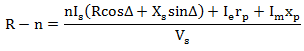
where, R is the ratio error
n is the turns ratio
Is is the secondary winding current
Ie is the iron loss component
Im is the magnetising component
It is seen from the above equation that the ratio error in a P.T. depends on the secondary current, magnetising and iron loss components of current.
5. In a P.T. values of components of currents are negligible.
a) True
b) False
Answer: b
Explanation: In a C.T. the various components of current such as magnetising current, iron loss component of current are almost comparable in magnitude with the value of the load current.
6. Ratio error can be minimised by _________
a) reducing the turns
b) reducing the current
c) increasing the voltage
d) using a good core material
Answer: d
Explanation: By making use of a good quality core material, low value of flux density and following required precautions in the core assembly we can minimise the value of the ratio error.
7. Another method of eliminating the ratio error is _________
a) by reducing secondary turns
b) by increasing the primary turns
c) by increasing secondary turns
d) by reducing the primary turns
Answer: a
Explanation: In a P.T., at no load, we get![]()
where, R is the ratio error
n is the turns ratio
Is is the secondary winding current
Ie is the iron loss component
Im is the magnetising component
From the above equation it is seen that to reduce the ratio error, actual ratio and nominal ratio must be made equal. This can be done by reducing the secondary turns.
8. How is the voltage ratio dependent on the frequency?
a) they are independent of each other
b) they aid each other
c) they oppose each other
d) depends on the setup of the circuit
Answer: c
Explanation: As the voltage ratio changes, the frequency also changes. It depends on the relative value of the core loss component Io as well as the leakage reactance. The effects due to the voltage ratio and the change in frequency oppose each other.
Characteristics of Potential Transformers
1. Increasing secondary burden _____________
a) increases Is
b) decreases Is
c) keeps Is constant
d) decreases Ip
Answer: a
Explanation: When the secondary burden of a potential transformer increases, it leads to an increase in the secondary current. As a result the primary current also increases.
2. For a given Vp the Vs __________
a) increases
b) decreases
c) remains constant
d) depends on the supply
Answer: b
Explanation: For a particular value of primary voltage Vp, the value of the secondary voltage Vs decreases. This leads to a decrease in the actual ratio.
3. What is effect of the secondary burden on the ratio error?
a) ratio error is constant with secondary burden
b) ratio error decreases with secondary burden
c) ratio error increases with secondary burden
d) depends on the supply voltage
Answer: c
Explanation: As the secondary burden is increased, the ratio error also increases and becomes more negative. Ratio error varies linearly with respect to the change in the secondary burden.
4. Vp is leading in phase, while Vs is lagging in phase.
a) True
b) False
Answer: a
Explanation: As the secondary burden is increased, winding voltage drop increases. Voltage Vp is leading in phase while Vs is lagging in phase. As a result the phase angle increases with the secondary burden.
5. What is the effect of p.f. on secondary burden?
a) Ip shifts towards Io
b) Ip deviates from Io
c) Ip is independent of Io
d) Ip and Io cancel eachother
Answer: a
Explanation: When the power factor of the secondary burden is reduced, Ip shifts towards Io. Voltages Vp and Vs come closer to Ep and Es.
6. How is the transformation ratio dependent on the secondary burden?
a) decreases
b) increases
c) remains constant
d) depends on the supply
Answer: b
Explanation: As the primary voltage Vp is constant, the induced primary e.m.f Ep is reduced. Similarly the secondary voltage Vs is reduced with respect to Es. As a result the transformation ratio increases.
7. Decrease in p.f. makes Vs to lead Vp.
a) True
b) False
Answer: a
Explanation: As the power factor is decreased, Vs leads in phase while Vp decreases in phase. Thus the phase angle reduces with the decrease in power factor (lagging).
8. At constant voltage how is frequency affected by flux?
a) decreases with an increase in flux
b) increases with a decrease in flux
c) remains constant
d) depends on the current
Answer: b
Explanation: When frequency is increased at a constant voltage, the flux decreases. Voltage ratio decreases as the magnetizing and iron loss components of current are reduced.
Advanced Problems on C.T. and P.T.
1. A 50 Hz, bar primary CT has a secondary with 800 turns. The secondary supplies 7 A current into a purely resistive burden of 2 Ω. The magnetizing ampere-turns are 300. The phase angle is?
a) 3.1°
b) 85.4°
c) 94.6°
d) 175.4°
Answer: a
Explanation: Secondary burden is purely resistive and the resistance of burden is equal to the resistance of the secondary winding; the resistance of secondary winding = 1Ω. The voltage induced in secondary × resistance of secondary winding = 7 × 2 = 14V. Secondary power factor is unity as the load is purely resistive. The loss component of no-load current is to be neglected i.e. Ie = 0. IM = 300 A.
Secondary winding current IS = 7 A
Reflected secondary winding current = n IS = 5600 A
∴ tan θ = IMnIS. So, θ = 3.1°.
2. A 50 Hz, bar primary CT has a secondary with 500 turns. The secondary supplies 5 A current into a purely resistive burden of 1 Ω. The magnetizing ampere-turns are 200. What is the ratio error at full load, if the iron loss is 1.5 W and magnetizing mmf is 100 A?
a) Zero
b) 45 μWb
c) 25.5 μWb
d) 100 μWb
Answer: b
Explanation: Voltage induced in the secondary,
ES = IS × ZS = 5 V
ES = 4.44 f ∅ N
∴ ∅ = ES4.44fN=54.44fN = 45 μWb.
Extension Of Instrument Ranges MCQs
3. A 1000/5 A, 50 Hz correct transformer has a secondary burden comprising a non-inductance of 1.6Ω. The flux in the core at full load is?
a) 160 μWb
b) 180 μWb
c) 200 μWb
d) 150 μWb
Answer: b
Explanation: Turn ratio = 1000/5 = 200
NP = 1
So, NS = 200
Secondary impedance = 1.6Ω
Secondary induced voltage, ES = 5 × 1.6 = 8 V
∴ ES = 4.44 f N ∅
So, ∅ = ES4.44fN=84.44fN = 180 μWb.
4. A 1000/5 A, 50 Hz correct transformer has a secondary burden comprising a non-inductance of 2Ω. What is the ratio error, if the iron loss is 3 W and magnetizing mmf is 250 A?
a) 4%
b) 5.7%
c) 3.6%
d) 4.8%
Answer: b
Explanation: E = 10200 V
I = 60 A
I = mmfNP = 250 A
Actual rating R = 200 + 605 = 212
So, percentage ratio error = Kn−RR × 100 = 200−212212 × 100 = 5.7%.
5. A 200/1 Current Transformer (CT) is wound with 400 turns on the secondary on a toroidal core. When it carries a current of 180 A on the primary, the ratio is found to be -0.5%. If the number of secondary turns is reduced by 1, the new ratio error (in %) will be?
a) 0.0
b) -0.5
c) -1.0
d) -2.0
Answer: c
Explanation: Turn compensation only alters ratio error n=400
Ratio error = -0.5% = – 0.5100 × 400 = -2
So, Actual ratio = R = n+1 = 401
Nominal Ratio KN = 400/1 = 400
Now, if the number of turns are reduced by one, n = 399, R = 400
Ratio error = KN−RR=200−200200 = 0.
6. A (350 A/ 7A), 50 Hz current transformer has a primary bar. The secondary burden is a pure resistance of 1 Ω and it draws a current of 5 A. The magnetic core requires 350 AT for magnetization. Find the percentage ratio error.
a) 10.56
b) -28.57
c) 11.80
d) -11.80
Answer: b
Explanation: Im = 350/1 = 350 A
Ip = ((nI2s)2+(I2m)2)0.5 = 490.05
n = 350/7 = 50
∴ R = IPIS=490.057 = 70
∴ Percentage ratio error = 50−7070 × 100 = -28.57%.
7. The observation when the secondary winding of a current transformer is open-circuited is?
a) The whole of the primary current produces a large value of flux in the core thereby producing a large voltage in the secondary winding
b) The large voltage may act as a safety hazard for the operators and many even raptures the insulation
c) When the large magnetizing force is taken off, it leaves a large value of residual magnetism
d) When the large magnetizing force is taken off, it leaves a small value of residual magnetism
Answer: b
Explanation: Never open the circuit of the secondary winding of a current transformer while to the primary winding is energized. Failure to observe this precaution may lead to serious consequences both to the operating personnel and to the transformer.
8. Usually a CT has ____________
a) Power overload capacity than PT
b) The same overload capacity as a PT
c) A higher overload capacity than a PT
d) No overload capacity
Answer: c
Explanation: A CT cannot have greater or same power overload than PT. Also, it will be having some load on it. This load is a higher overload capacity than a PT.
9. A PT is a device which is ___________
a) Electrostatically coupled
b) Electrically coupled
c) Electromagnetically coupled
d) Conductively coupled
Answer: c
Explanation: A Potential Transformer cannot be electrostatically coupled since CRO are electrostatically coupled. Also, they cannot be conductively coupled. But since they are kind of electrically coupled hence electromagnetically coupled is the only correct option.
10. The CT supplies current to the current coil of a wattmeter power factor meter, energy meter and, an ammeter. These are connected as?
a) All coils in parallel
b) All coils in series
c) Series-parallel connection with two in each arm
d) Series-parallel connection with one in each arm
Answer: b
Explanation: Since the CT supplies the current to the current coil of a wattmeter, therefore the coils are connected in series so that the current remains the same. If they were connected in parallel then the voltages would have been the same but the currents would not be the same and thus efficiency would decrease.
Advanced Problems on Indicating Instruments – 1
1. In a moving iron meter, the deflection torque is proportional to?
a) Square of the current through the coil
b) Current through the coil
c) Sine of measurand
d) The Square root of the measurand
Answer: a
Explanation: We know that,
Td = 12I2dldθ
∴ The deflection torque is proportional to the square of the current through the coil.
2. The full-scale deflection current of an ammeter is 4 mA and its internal resistance is 400Ω. If this meter is to have a full deflection of 10 A, what is the value of the shunt resistance to be used?
a) 49.99 Ω
b) 0.16 Ω
c) 1.5 Ω
d) 2.6 Ω
Answer: b
Explanation: Voltage across the meter = 4 × 10-3 × 4 × 102 = 1.6 V
Current through the shunt = 10 – 0.004 = 9.996 A
∴ Shunt resistance = 1610×9.996 = 0.16 Ω.
3. The full-scale deflection current of a meter is 4 mA and its internal resistance is 400Ω. This meter is to have full deflection when 400 V is measured. What is the value of the series resistor to be used?
a) 99.90 kΩ
b) 100 kΩ
c) 99.60 kΩ
d) 100 Ω
Answer: c
Explanation: (RS + 400) × 10-3 × 4 = 400
Or, RS = 100000 – 400 = 99.6 kΩ.
4. Two ammeters, one with a full-scale current of 1 mA and internal resistance of 100 Ω and other a full-scale current of 10 mA and internal resistance of 25 Ω are in parallel. What is the total current, these two meters can carry without the reading out of scale in any meter?
a) 1 mA
b) 10 mA
c) 11 mA
d) 5 mA
Answer: d
Explanation: The lower current Il will decide the total current.
∴ T × 25125 = 1 mA
Or, T = 5 mA.
5. A meter has a full scale of 90° at a current of 1 A. This meter has a perfect square law response. What is the current when the deflection angle is 45°?
a) 0.5 A
b) 0.25 A
c) 0.707 A
d) 0.67 A
Answer: c
Explanation: We know, TD = Cθ
Also, TD = KI2
∴ I2 = CK θ = C’θ
Or, I2I=C′πC′π2=12
So, I = 0.707 A.
6. The scale of a dynamometer type instrument marked in terms of RMS value would be__________
a) Uniform throughout
b) Non-uniform and crowded near the full scale
c) Non-uniform and crowded at the beginning
d) Non-uniform and crowded around mid-scale
Answer: c
Explanation: We have deflection θ ∝ I2 for an ammeter and θ ∝ V2 for a voltmeter. We have assumed the value for the voltmeter to be constant but it is not true. The value is constant for a radical field but not for a voltmeter.
7. Moving Iron Instrument can be used as ____________
a) An ammeter for measuring DC as well as AC
b) For measuring DC current and voltages only
c) An ammeter and a voltmeter for measuring DC as well as AC
d) For measuring AC current and voltages only
Answer: c
Explanation: When the instrument is connected in the circuit, the current flows through the coil. These currents set up a magnetic field in the coil. The result is that the pointer attached to the moving system moves from zero position. If the current in the coil is reversed, the direction of deflecting torque remains unchanged. Therefore, these instruments can be used for both DC as well as AC measurements.
8. A 10 mA PMMC ammeter reads 4 mA in a circuit. Its bottom control spring snaps suddenly. The meter will now show __________
a) 10 mA
b) 8 mA
c) 2 mA
d) Zero
Answer: d
Explanation: The spring gives the controlling torque. It is connected in series with the coil. If the spring is cut open, there will be no deflection.
9. The standardization of AC potentiometer is done by ____________
a) Using a DC standard source and d’ Arsonval galvanometer
b) Using AC standard sources and transfer instruments
c) Using a standard AC voltage source
d) Using a DC standard source and transfer instruments
Answer: d
Explanation: Standardization of AC potentiometer is done with the help of standard DC source i.e., a standard cell or a Zener source and a transfer instrument where transfer instrument may be an electrodynamometer or a thermocouple instrument.
10. The inductance of a certain moving- iron ammeter is expressed as L = 10 + 3θ – θ24 μH, where θ is the deflection in radian from the zero position. The control spring torque is 25 × 10-6 Nm/rad. The meter carries a current of 5 A. What is the deflection?
a) 2.4
b) 2.0
c) 1.2
d) 1.0
Answer: c
Explanation: At equilibrium,
Kθ = 12I2dldθ
(25 × 10-6) θ = 12I2(3–θ2) × 10-6
∴ 2 θ + θ2 = 3
Or, θ = 1.2.
Advanced Problems on Indicating Instruments – 2
1. A current of – 8 + 62–√ (sin (ωt + 30°)) A is passed through three meters. The respective readings (in ampere) will be?
a) 8, 6 and 10
b) 8, 6 and 8
c) – 8, 10 and 10
d) -8, 2 and 2
Answer: c
Explanation: PMMC instrument reads only DC value and since it is a centre zero type, so it will give – 8 values.
So, rms = 82+(62√2√)2−−−−−−−−−√ = 10 A
Moving iron also reads rms value, so its reading will also be 10 A.
2. A rectifier type AC voltmeter consists of a series resistance R, an ideal full-wave rectifier bridge and a PMMC instrument. The internal resistance of the instrument is 100 Ω and a full- scale deflection is produced by a DC current of 1 mA. A voltage of 100 V (rms) is applied to the input terminals. The value of R required is?
a) 63.56 Ω
b) 89.83 Ω
c) 89.83 kΩ
d) 141.3 kΩ
Answer: c
Explanation: VOAverage = 0.636 × 2–√ Vrms = 0.8993 Vrms
The deflection with AC is 0.8993 times that with DC for the same value of voltage V
SAC = 0.8993 SDC
SDC of a rectifier type instrument is 1Ifs where Ifs is the current required to produce full scale deflection, Ifs = 1 mA; Rm = 100 Ω; SDC = 103 Ω/V
SAC = 0.8993 × 1000 = 899.3 Ω/V. Resistance of multiplier RS = SAC V – Rm – 2Rd, where Rd is the resistance of diode, for ideal diode Rd = 0
∴ RS = 899.3 × 100 – 100 = 89.83 kΩ.
3. A current of [2 + 2–√ sin (314t + 30) + 22–√ cos (952t +45)] is measured with a thermocouple type, 5A full scale, class 1 meter. The meter reading would lie in the range?
a) 5 A ± 1 %
b) (2 + 32–√) A ± 1%
c) 3 A ± 1.7 %
d) 2 A ± 2.5 %
Answer: c
Explanation: I = [2 + 2–√ sin (314t +30°) + 22–√ cos (952t + 45°)] Thermocouple measure the rms value of current.
Irms = [22+(2√2√)2+(22√2√)2]1/2=9–√ = 3 A ± 1.7%.
4. A 50 Hz voltage is measured with a moving iron voltmeter and a rectifier type AC voltmeter connected in parallel. If the meter readings are Va and Vb respectively. Then the form factor may be estimated as?
a) VaVb
b) 1.11VaVb
c) 2√VaVb
d) πVaVb
Answer: b
Explanation: Form factor of the wave = RMSvalueMeanvalue
Moving iron instrument will show rms value. Rectifier voltmeter is calibrated to read rms value of the sinusoidal voltage that is, with form factor of 1.11.
∴ Mean value of the applied voltage = Vb1.11
∴ Form factor = VaVb/1.11=1.11VaVb
5. A moving iron ammeter produces a full-scale torque of 240 μN-m with a deflection of 120° at a current of 10 A. the rate of change of self-inductance (μH/rad) of the instrument at full scale is?
a) 2.0 μH/rad
b) 4.8 μH/rad
c) 12.0 μH/rad
d) 114.6 μH/rad
Answer: b
Explanation: At full scale position, 12I2dLdθ = TC
12102dLdθ = 240 × 10-6
∴ dLdθ = 4.8 μH/rad.
6. A moving coil of a meter has 250 turns and a length and depth of 40 mm and 30 mm respectively. It is positioned in a uniform radial flux density of 450 mT. The coil carries a current of 160 mA. The torque on the coil is?
a) 0.0216 N-m
b) 0.0456 N-m
c) 0.1448 N-m
d) 1 N-m
Answer: a
Explanation: Given, N = 250, L = 40 × 10-3, d = 30 × 10-3m, I = 160 × 10-3A, B = 450 × 10-3 T
Torque = 250 × 450 × 10-3 × 40 × 10-3 × 30 × 10-3 × 160 × 10-3 = 200 × 10-6N-m = 0.0216 N-m.
7. Two 100 μA full-scale PMMC meters are employed to construct a 10 V and a 100 V full-scale voltmeter. These meters will have figure of merit (sensitivities) as?
a) 10 kΩ/V and 10 kΩ/V
b) 100 kΩ/V and 10 kΩ/V
c) 10 kΩ/V and 100 kΩ/V
d) 10 kΩ/V and 1 kΩ/V
Answer: a
Explanation: SV = 1ISS = current required for full scale deflection
SV = 1100×10−6 = 10 kΩ/V.
8. A PMMC rated as 100 μA is used in a rectifier type of instrument which uses full wave rectification. What is the sensitivity on sinusoidal AC?
a) 4.5 kΩ/V
b) 18 kΩ/V
c) 10 kΩ/V
d) 9 kΩ/V
Answer: d
Explanation: Sensitivity = 1100×10−6 = 10 kΩ/V
For full-wave rectification SAC = 0.9 + SDC = 0.9 × 10 = 9kΩ/V.
9. The discharge of a capacitor through a ballistic galvanometer produces a damped frequency of 0.125 Hz and successive swings of 120, 96 and 76.8 mm. The damping ratio is?
a) 0.0568
b) 0.0887
c) 0.0357
d) 0.0441
Answer: c
Explanation: Logarithmic decrement, δ = lnx1x2=ln12096 = 0.225
Now, δ is related to damping ratio K as, K = 1(1+(2πδ)2)0.5
K = 1(1+(2π0.225)2)0.5
∴ K = 0.0357.
10. The discharge of a capacitor through a ballistic galvanometer produces a damped frequency of 0.125 Hz and successive swings of 120, 96 and 76.8 mm. The logarithmic decrement is?
a) 0.225
b) 0.565
c) 0.484
d) 0.7887
Answer: a
Explanation: Logarithmic decrement, δ = lnx1x2=ln12096 = 0.225
Now, δ is related to damping ratio K as, K = 1(1+(2πδ)2)0.5
K = 1(1+(2π0.225)2)0.5
∴ K = 0.0357.