Most Updated Operational Amplifier MCQs ( Electric Circuits ) MCQs – Competitive Electric Circuits MCQs

Latest Electric Circuits MCQs
By practicing these MCQs of Operational Amplifier MCQs ( Electric Circuits ) MCQs – Latest Competitive MCQs , an individual for exams performs better than before. This post comprising of objective questions and answers related to “Operational Amplifier MCQs ( Electric Circuits ) Mcqs “. As wise people believe “Perfect Practice make a Man Perfect”. It is therefore practice these mcqs of Electric Circuitsto approach the success. Tab this page to check “Operational Amplifier MCQs ( Electric Circuits )” for the preparation of competitive mcqs, FPSC mcqs, PPSC mcqs, SPSC mcqs, KPPSC mcqs, AJKPSC mcqs, BPSC mcqs, NTS mcqs, PTS mcqs, OTS mcqs, Atomic Energy mcqs, Pak Army mcqs, Pak Navy mcqs, CTS mcqs, ETEA mcqs and others.
Operational Amplifier MCQs ( Electric Circuits ) MCQs – Electric Circuits MCQs
The most occurred mcqs of Operational Amplifier MCQs ( Electric Circuits ) in past papers. Past papers of Operational Amplifier MCQs ( Electric Circuits ) Mcqs. Past papers of Operational Amplifier MCQs ( Electric Circuits ) Mcqs . Mcqs are the necessary part of any competitive / job related exams. The Mcqs having specific numbers in any written test. It is therefore everyone have to learn / remember the related Operational Amplifier MCQs ( Electric Circuits ) Mcqs. The Important series of Operational Amplifier MCQs ( Electric Circuits ) Mcqs are given below:
Operational Amplifier Terminals, Terminal Voltages and Currents
1. Op-amp was introduced by __________
a) Fairchild
b) Maxwell
c) Rutherford
d) Sahani
Answer: a
Explanation: Op-amp was introduced by Fairchild semiconductor in 1968.
2. The number of terminals in an Op-amp ______________
a) 6
b) 2
c) 5
d) 3
Answer: c
Explanation: Inverting input, the Non-inverting input, Output, Positive power supply, Negative power supply.
3. The Op-amp is a type of ___________
a) Differential amplifier
b) Integrated amplifier
c) Isolation amplifier
d) Feedback amplifier
Answer: a
Explanation: The Op-amp is a type of differential amplifier.
4. In the circuit of Op-amp given V- stands for _________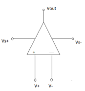
a) Non-inverting input
b) Non-inverting output
c) Inverting input
d) Inverting output
Answer: c
Explanation: V+: Non-inverting input and V- : Inverting input.
5. When the input voltage difference is small in magnitude, the Op-amp behaves as ____________
a) Non-linear device
b) Linear device
c) Complex device
d) Bipolar device
Answer: b
Explanation: When │vp-vn│is small then Op-amp acts as a linear device as the output voltage is a linear function of input voltages.
6. If the output voltage is not a linear function of input voltage then ____________
a) Op-amp acts a linear device
b) Op-amp acts as a non-linear device
c) Op-amp acts a polar device
d) Op-amp acts as an inverter
Answer: b
Explanation: If output voltage is not a linear function of input voltage then Op-amp acts as a non-linear device.
7. The negative feedback causes the input voltage difference to ____________
a) 1
b) Increase
c) Decrease
d) 0
Answer: c
Explanation: Negative feedback means a signal is fed back from output terminals to the non-inverting input terminals and this results in a decrease in input voltage difference.
8. Find the gain for the following circuit.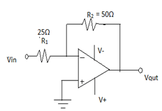
a) -2
b) 2
c) -1
d) 1
Answer: a
Explanation: In this circuit, the only node is at the negative terminal of the Op-amp (say Vn) and by ideal rules of Op-amp, Vn= Vp =0(in this circuit). Gain= Vout/Vin= -R2/R1.
9. Calculate the gain for the Op-amp given.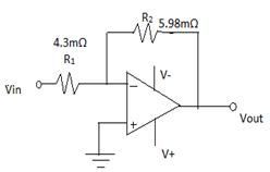
a) 0.719
b) 2.572
c) 1.390
d) 1.237
Answer: c
Explanation: Gain= Vout/Vin= -R2/R1 = -5.98*10-3/4.3*10-3.
10. Given Op-amp is ideal. Calculate vo if va=1v and vb=0v.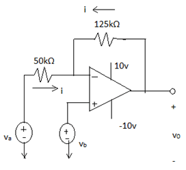
a) -4v
b) -2.5v
c) 4v
d) 2.5v
Answer: b
Explanation: In the given circuit, a negative feedback exists between Op-amp’s output and its inverting input (voltage here is 0, as vp =vb=0 and vn=vp). Node-voltage equation is i50=i125=i0.
i50= (va-vn)/50 =1/50 mA.
I125= (v0-vn)/125 = v0/125 mA.
1/50 + v0/125 = 0.
v0 is -2.5volts.
The Inverting and Non-Inverting Amplifier Circuit
1. The opamp in the Inverting circuit is in __________
a) Linear region
b) Saturation
c) Cut-off region
d) Non-linear region
Answer: a
Explanation: We assume that the opamp is in linear region.
2. In an Inverting Amplifier circuit, the output voltage vo is expressed as a function of ____________
a) Input current
b) Output current
c) Source voltage
d) Source current
Answer: c
Explanation: The goal of an inverting circuit is to express output voltage vo as a function of source voltage vs.
Simple Resistive Circuits MCQs
3. The other name for Gain is ____________
a) Scaling factor
b) Output
c) Amplifying factor
d) Scaling level
Answer: a
Explanation: The gain is also known as scaling factor and it is the ratio of Rf/Rs in case of an Inverting amplifying circuit.
4. If VCC = 12V and vs=1mV, then Rf/Rs is _____________
a) >12000
b) <12000
c) 12000
d) 1
Answer: b
Explanation: Rf/Rs ≤ │VCC/vs│.
5. In the expression vo= -Avn, A is called ______________
a) Closed loop gain
b) Closed loop fault
c) Open loop fault
d) Open loop gain
Answer: d
Explanation: A is called open loop gain.
6. The circuits of an inverting and Non-Inverting amplifying comprises of __________ and _______ number of resistors.
a) 3, 2
b) 2, 3
c) 2, 2
d) 3, 3
Answer: b
Explanation: Inverting amplifying circuit- Rs, Rf.
Non-Inverting amplifying circuit – Rs, Rf, Rg.
7. The condition for a Non-inverting amplifying circuit to operate in linear region operation _____________
a) (Rs+Rf)/Rs < │VCC/vg│
b) (Rs+Rf)/Rs ≠ │VCC/vg│
c) (Rs+Rf)/Rs > │VCC/vg│
d) (Rs+Rf)/Rs = │VCC/vg│
Answer: a
Explanation: Assume that opamp is ideal. The condition for the linear region operation in a Non-inverting amplifying circuit is (Rs+Rf)/Rs <│VCC/vg│.
8. If Rs= 3Ω, Rf= 6Ω then the relation between vo and vg in case of a Non-Inverting amplifying circuit.
a) vo= 9vg
b) vo= 6vg
c) vo= 3vg
d) vo= vg
Answer: c
Explanation: vo= ((Rs+Rf)/Rs) *vg.
9. If Rs= 5Ω, Rf= 25Ω and -2.5V ≤ vg ≤ 2.5V. What are the smallest power supply voltages that could be applied and still have opamp in linear region?
a) ±9V
b) ±2.5V
c) ±6V
d) ±15V
Answer: d
Explanation: vo= ((Rs+Rf)/Rs) *vg. By substituting the values, we have vo=6vg.
vo=6(-2.5) = -15
vo=6(2.5) =15.
10. If an inverting amplifying circuit has a gain of 10 and ±15V power supplies are used. The values of input for which opamp would be in the linear region?
a) ±1.25
b) ±1.5V
c) ±2.25
d) ±0.5
Answer: b
Explanation: Gain= Rf/Rs= 10 and vo= (-Rf/Rs)*vs.
→ vo= -10vs and given -12V≤ vo ≤ 12V.
→ -15= -10vs. So, vs= 1.5V
→ 15=-10vs. So, vs=-1.5V.
11. If the gain of an inverting amplifying circuit is 13 and ±22V power supplies are used. What range of input values allows the opamp to be in linear region?
a) ±1.69
b) ±1.35V
c) ±2.28
d) ±0.5
Answer: a
Explanation: Gain= Rf/Rs= 13 and vo= (-Rf/Rs)*vs.
→ vo= -13vs and given -22V≤ vo ≤ 22V.
→ -22= -13vs. So, vs=1.692 V
→ 22=-13vs. So, vs=-1.692V.
12. The input applied to an Inverting amplifier is ______________
a) Equal to output
b) Equal to Inverted output
c) Not equal to output
d) Output is equal to input
Answer: b
Explanation: The name itself indicates it is an Inverting amplifier. So, the input applied is inverted and is given as output. Suppose the input applied is sinusoidal then, the output is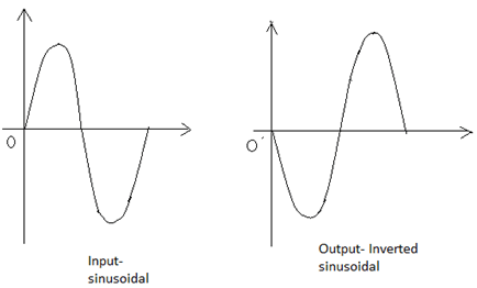
13. In R1=10kΩ, Rf=100kΩ, v1=1V. A load of 25kΩ is connected to the output terminal. Calculate i1 and vo.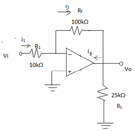
a) 0.5mA, 10V
b) 0.1mA, 10V
c) 0.1mA, -10V
d) 0.5mA, -10V
Answer: c
Explanation: i1= v1/R1 = 1V/10kΩ = 0.1mA
V0= -(Rf/R1)*v1 = -(100kΩ/10kΩ)*1V = -10V.
Most Updated Operational Amplifier MCQs ( Electric Circuits ) MCQs – Competitive Electric Circuits MCQs