Network Theory and Complex Circuit Diagram MCQs ( Network Theory ) MCQs – Network Theory MCQs

Latest Network Theory MCQs
By practicing these MCQs of Network Theory and Complex Circuit Diagram MCQs ( Network Theory ) MCQs – Latest Competitive MCQs , an individual for exams performs better than before. This post comprising of objective questions and answers related to “ Network Theory and Complex Circuit Diagram MCQs ( Network Theory ) Mcqs “. As wise people believe “Perfect Practice make a Man Perfect”. It is therefore practice these mcqs of Network Theory to approach the success. Tab this page to check ” Network Theory and Complex Circuit Diagram MCQs ( Network Theory )” for the preparation of competitive mcqs, FPSC mcqs, PPSC mcqs, SPSC mcqs, KPPSC mcqs, AJKPSC mcqs, BPSC mcqs, NTS mcqs, PTS mcqs, OTS mcqs, Atomic Energy mcqs, Pak Army mcqs, Pak Navy mcqs, CTS mcqs, ETEA mcqs and others.
Network Theory MCQs – Network Theory and Complex Circuit Diagram MCQs ( Network Theory ) MCQs
The most occurred mcqs of Network Theory and Complex Circuit Diagram MCQs ( Network Theory ) in past papers. Past papers of Network Theory and Complex Circuit Diagram MCQs ( Network Theory ) Mcqs. Past papers of Network Theory and Complex Circuit Diagram MCQs ( Network Theory ) Mcqs . Mcqs are the necessary part of any competitive / job related exams. The Mcqs having specific numbers in any written test. It is therefore everyone have to learn / remember the related Network Theory and Complex Circuit Diagram MCQs ( Network Theory ) Mcqs. The Important series of Network Theory and Complex Circuit Diagram MCQs ( Network Theory ) Mcqs are given below:
Advanced Problems on Network Theory – 1
1. Branch current and loop current relation is expressed in matrix form shown below, where Ij represents branch current and Ik represents loop current.
[I1; I2; I3; I4; I5; I6; I7; I8] = [0 0 1 0; -1 -1 -1 0; 0 1 0 0; 1 0 0 0; 0 0 -1 -1; 1 1 0 -1; 1 0 0 0; 0 0 0 1] [I1; I2; I3; I4] The rank of the incidence matrix is?
a) 4
b) 5
c) 6
d) 8
Answer: a
Explanation: Number of branches b = 8
Number of links l = 4
Number of twigs t = b – l = 4
Rank of matrix = n – 1 = t = 4.
2. A capacitor, used for power factor correction in a single phase circuit decreases which of the following?
a) Power factor
b) Line current
c) Both Line current and Power factor
d) Neither Line current nor Power factor
Answer: b
Explanation: We know that a capacitor is used to increase the Power factor. However, with decrease in line current the power factor is increased. Hence line current decreases.
3. D is the distance between the plates of a parallel plate capacitor. The dielectric constants are ∈1 and ∈2 respectively. The total capacitance is proportional to ____________
a) ∈1∈2∈1+∈2
b) ∈1 – ∈2
c) ∈1∈2
d) ∈1 ∈2
Answer: a
Explanation: The combination is equal to two capacitors in series.
So, C = [∈0∈1(A0.5d)][∈0∈2(A0.5d)]∈0∈1A0.5d+∈0∈1A0.5d
Hence, C is proportional to ∈1∈2∈1+∈2.
4. A two branch circuit has a coil of resistance R1, inductance L1 in one branch and capacitance C2 in the second branch. If R is increased, the dynamic resistance is going to ___________
a) Increase
b) Decrease
c) Remains constant
d) May increase or decrease
Answer: b
Explanation: We know that,
Dynamic resistance = L1R1C2
So, if R1 is increased, keeping Inductance and Capacitance same, so The Dynamic resistance will decrease, as the denomination is increasing.
5. A 1 μF capacitor is connected to 12 V batteries. The energy stored in the capacitor is _____________
a) 12 x 10-6 J
b) 24 x 10-6 J
c) 60 x 10-6 J
d) 72 x 10-6 J
Answer: d
Explanation: We know that,
Energy, E = 0.5 CV2
= 0.5 X 1 X 10-6 X 144
= 72 x 10-6 J.
6. For the two circuits shown below, the relation between IA and IB is ________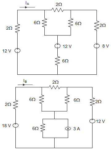
a) IB = IA + 6
b) IB = IA + 2
c) IB = 1.5IA
d) IB = IA
Answer: c
Explanation: In the circuit of figure (IB), transforming 3A source into 18 V source, all sources are 1.5 times of that in circuit (IA). Hence, IB = 1.5IA.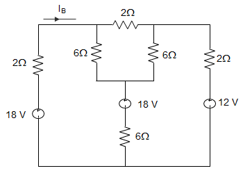
7. For the circuit given below, the current I in the circuit is ________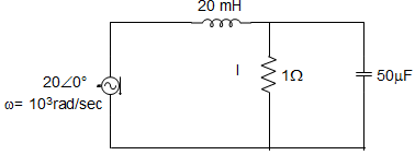
a) –j1 A
b) J1 A
c) Zero
d) 20 A
Answer: a
Explanation: XEQ = sL + R×1/sCR+1/sC=sL+R1+sRC
IO = VXEQ
∴ I = XCXC+R IO
= 1/sC1sC+R×VsL(1+sRC)+R(1+sRC)
= 11+sRC×VsL(1+sRC)+R(1+sRC)
= VsL(1+sRC)+R
= Vj×103×20×10−3(1+j×103×50×10−6+1)
= V20j(1+j50×10−3)+1
= V20j−1+1=2020j = -j1 A.
8. An AC source of RMS voltage 20 V with internal impedance ZS = (1+2j) Ω feeds a load of impedance ZL = (7+4j) Ω in the circuit given below. The reactive power is _________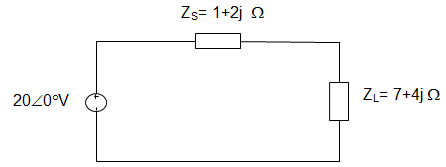
a) 8 VAR
b) 16 VAR
c) 28 VAR
d) 32 VAR
Answer: b
Explanation: Current I = VZL+ZS=20∠0°8+6j
= 2082+62√=∠0°∠arctan(34)
= 2010 ∠-arc tan(34)
= 2∠-arc tan(34)
Power consumed by load = |I|2ZL
= 4(7+4j)
= 28 + j16
∴ The reactive power = 16 VAR.
9. In the circuit given below, RI = 1 MΩ, RO = 10 Ω, A = 106 and VI = 1μV. Then the output voltage, input impedance and output impedance respectively are _________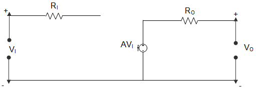
a) 1 V, ∞ and 10 Ω
b) 1 V, 0 and 10 Ω
c) 1V, 0 and ∞
d) 10 V, ∞ and 10 Ω
Answer: a
Explanation: VO (output voltage) = AVI = 106 × 10-6 = 1 V
V1 = Z11 I1 + Z12 I2
V2 = Z21 I1 + Z22 I2
Here, I1 = 0
Z11 = V1I1=VO0 = ∞
Z22 = V2I2=AVII2
Or, Z22 = 1I2 = RO = 10 Ω.
10. If operator ‘a’ = 1 ∠120°. Then (1 – a) is equal to ____________
a) 3–√
b) 3–√∠-30°
c) 3–√∠30°
d) 3–√∠60°
Answer: b
Explanation: Given that, ‘a’ = 1 ∠120°
So, 1 – a = 1 – 1∠120°
= 1 + 0.5 – j 0.866
= 1.5 – j 0.866
= 3∠-30°.
11. For making a capacitor, the dielectric should have __________
a) High relative permittivity
b) Low relative permittivity
c) Relative permittivity = 1
d) Relative permittivity neither too high nor too low
Answer: a
Explanation: Relative permittivity is for ideal dielectric which is air. Achieving such a precise dielectric is very difficult.
Low relative permittivity will lead to low value of capacitance.
High relative permittivity will lead to a higher value of capacitance.
12. In the circuit shown below, the voltage V will be __________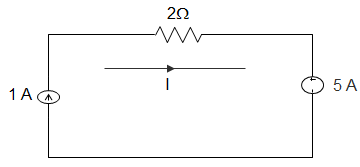
a) – 3V
b) Zero
c) 3 V
d) 5 V
Answer: a
Explanation: By applying KVL, I = 1 A
VAB – 2 × 1 + 5 = 0
Or, VAB = -3 V.
13. If A = 3 + j1, then A4 is equal to __________
a) 3.16 ∠18.4°
b) 100 ∠73.72°
c) 100 ∠18.4°
d) 3.16 ∠73.22°
Answer: b
Explanation: Given A = 3 + j1
So, 3 + j1 = 10∠18.43°
Or, 3 + j1 = (10)4 ∠4 X 18.43°
= 100∠73.72°.
14. In the figures given below, Value of RA, RB and RC are 20 Ω, 10 Ω and 10 Ω respectively. The resistances R1, R2 and R3 in Ω are ________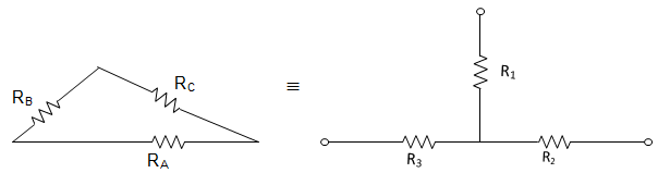
a) 2.5, 5 and 5
b) 5, 2.5 and 5
c) 5, 5 and 2.5
d) 2.5, 5 and 2.5
Answer: a
Explanation: R1 = RBRCRA+RB+RC=10040 = 2.5 Ω
R2 = RARCRA+RB+RC=20040 = 5 Ω
R3 = RBRARA+RB+RC=20040 = 5 Ω.
15. The resistance of a thermistor decreases with increases in __________
a) temperature
b) circuit
c) light control
d) sensors
Answer: b
Explanation: The resistance of a thermistor decreases with increases in temperature. Hence, it is used to monitor hot spot temperature of electric machines.
Advanced Problems on Network Theory – 2
1. In the circuit given below, the value of R is _________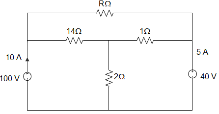
a) 10 Ω
b) 18 Ω
c) 24 Ω
d) 12 Ω
Answer: d
Explanation: By KCL,
∴ VP−401+VP−10014+VP2 = 0
Or, 22 VP = 660
∴ VP = 30 V
Potential difference between node x and y = 60 V
∴ -I – 5 + 40−30I = 0
Or, I = 5 A
∴ R = 605= 12 Ω.
2. In the circuit given below, the resistance between terminals A and B is 7Ω, between terminals B and C is 12Ω and between terminals C and A is 10Ω. The remaining one terminal in each case is assumed to be open. Then the value of RA and RB are _________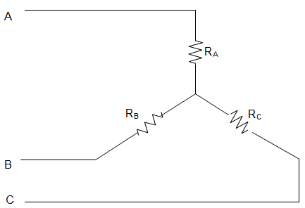
a) RA = 9 Ω and RB = 7 Ω
b) RA = 2.5 Ω and RB = 4.5 Ω
c) RA = 3 Ω and RB = 3 Ω
d) RA = 5 Ω and RB = 1 Ω
Answer: b
Explanation: Given RA + RB = 7 with C open
RB + RC = 12 with A as open
RA + RC = 10 with B open
Then, RA + RB + RC = 292 = 14.5
Hence, RA = 2.5 Ω, RB = 4.5 Ω and RC = 7.5 Ω.
3. Currents I1, I2 and I3 meet at a junction in a circuit. All currents are marked as entering the node. If I1 = -6sin(ωt) mA and I2 = 8 cos(ωt) mA, the I3 is ________
a) 10 cos(ωt + 36.87) mA
b) 14 cos(ωt + 36.87) mA
c) -14 sin(ωt + 36.87) mA
d) -10 cos(ωt + 36.87) mA
Answer: d
Explanation: Applying KCL, we get, I1 + I2 + I3 = 0
∴ -6 sin(ωt) + 8 cos(ωt) + I3 = 0
∴ I3 = 6 sin (ωt) – 8 cos (ωt)
= 10[sin (ωt).sin (36.86) – cos (ωt) cos (36.86)]
=-10[cos (ωt) cos (36.86) – sin (ωt) sin (36.86)]
= -10 cos (ωt + 36.86)
[As, cos (A+B) = cosA.cosB – sinA.sinB].
4. Viewed from the terminals A and B the circuit given below can be reduced to an equivalent circuit with a single voltage source in series with a resistor with ________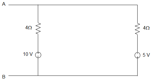
a) 5 V source in series with 10 Ω resistor
b) 1 V source in series with 2.4 Ω resistor
c) 15 V source in series with 2.4 Ω resistor
d) 1 V source in series with 10 Ω resistor
Answer: b
Explanation: Applying Thevenin’s Theorem REQ = 6 || 4
= 6×46+4
= 2410 = 2.4 Ω
VAB = 10 – 6 × (1510) = 1 V.
5. In the circuit given below, the voltage across the 2Ω resistor is ________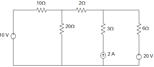
a) 3.41 V
b) -3.41 V
c) 3.8 V
d) -3.8 V
Answer: b
Explanation: Applying KCL to node A, VA−1010+VA20+VA7 = 0
Or, VA (0.1 + 0.05 + 0.143) = 1
Or, VA = 3.41 V
The voltage across the 2 Ω resistor due to 10 V source is V2 = VA7×2 = 0.97 V
V2Ω due to 20 V source, VA10+VA20+VA−207 = 0
Or, 0.1 VA + 0.05VA + 0.143VA = 2.86
∴ VA = 2.860.293 = 9.76 V
V2Ω = VA−207 × 2 = -2.92 V
The current in 2 Ω resistor = 2 × 55+8.67
= 1013.67 = 0.73 A
The voltage across the 2 Ω resistor = 0.73 × 2 = 1.46 V
V2Ω = 0.97 – 2.92 -1.46 = -3.41 V.
6. In the circuit given below, the value of IX using nodal analysis is _______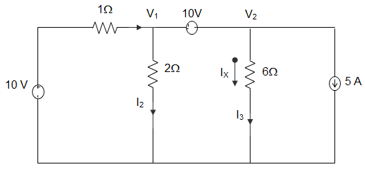
a) -2.5 A
b) 2.5 A
c) 5 A
d) -5 A
Answer: b
Explanation: Applying KCL, we get, I1 + 5 = I2 + I3
∴ 10–V11+5=V12+V26
∴ 30 – 3V1 + 15 = 3V1 + V2
∴ 6 V1 + V2 = 45
From voltage source, V2 – V1 = 10
Now, 7 V1 = 35, V1 = 5 V
And V2 = 15 V
∴ IX = V26=156 = 2.5 A.
7. In the circuit given below, the values of V1 and V2 respectively are _________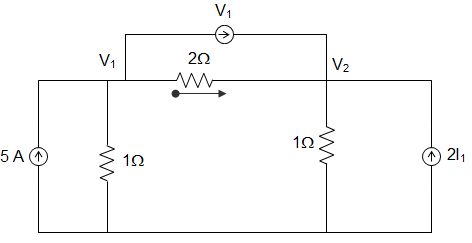
a) 0 and 5V
b) 5 and 0 V
c) 5 and 5 V
d) 2.5 and 2.5 V
Answer: d
Explanation: I1 = V1−V22
Applying KCL at node 1, 5 = V11+V1−V22+V1
10 = 2V1 + V1 – V2 + 2V1
Or, 10 = 5V1 – V2
KCL at node 2, V1−V22 + V1 + 2I1 = V2
∴ 1.5 V1 – V2 = 0
∴ V1 = V2 = 2.5 V.
8. In the circuit given below, the voltage across the 18 Ω resistor is 90 V. The voltage across the combined circuit is _________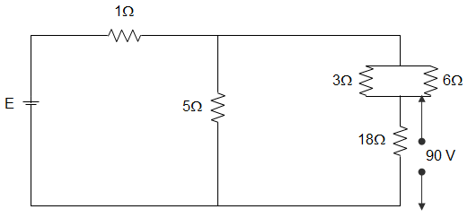
a) 125 V
b) 16 V
c) 24 V
d) 40 V
Answer: a
Explanation: Current through the 18 Ω resistance = 9018 = 5 A
Equivalent resistance of 3 Ω and 7 Ω banks = 3×63+6 = 2 Ω
Since, this 2 Ω resistance is in series with 18 Ω resistance, therefore total resistance = 18 + 2 = 20 Ω
This 20 Ω resistance is in parallel with 5 Ω resistance = 5×205+20 = 4 Ω
Hence, total resistance of the circuit = 1 + 4 = 5 Ω
Current through this branch = 5 A
∴ Voltage across dc= 5 × 20 = 100 V
Hence current through 5 Ω resistance = 1005 = 20 A
∴ Total current = 20 + 5 = 25 A
Since, total resistance of the circuit is 5 Ω therefore, voltage E = 25 × 5 = 125 V.
9. In the circuit given below, the value of R in the circuit, when the current is zero in the branch CD is _________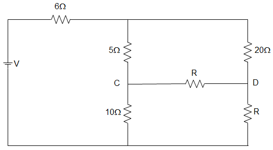
a) 10 Ω
b) 20 Ω
c) 30 Ω
d) 40 Ω
Answer: d
Explanation: The current in the branch CD is zero if the potential difference in the branch CD is zero.
That is, VC = VD
Or, V10 = VC = VD = VA × 1015
VR = VA × R20+R
And V10 = VR
∴ VA × 1015 = VA × RR+20 ∴ R = 40 Ω.
Elements of Realizability and Synthesis of One-Port Networks
10. Two capacitors of 0.5 μF and 1.5 μF capacitance are connected in parallel across a 110 V dc battery. The charges across the two capacitors after getting charged is ___________
a) 55 μC each
b) 275 μC each
c) 55 μC and 275 μC respectively
d) 275 μC and 55 μC respectively
Answer: c
Explanation: Q1 = 0.5 x 10-6 x 110
= 55 μC.
Also, Q2 = 2.5 x 10-6 x 110
= 275 μC.
11. Consider a circuit having resistances 2 Ω and 2 Ω in series with an inductor of inductance 2 H. The circuit is excited by a voltage of 12 V. A switch S is placed across the first resistance. Battery has remained switched on for a long time. The current i(t) after switch is closed at t=0 is _____________
a) 6
b) 6 – 3e-t
c) 6 + 3e-t
d) 3 – 6e-t
Answer: b
Explanation: From the figure, we can infer that,
I(t) = 1212(1–24e−t)
= 6 – 3e-t.
12. A resistance R is connected to a voltage source V having internal resistance RI. A voltmeter of resistance R2 is used to measure the voltage across R. The reading of the voltmeter is _____________
a) VSR1R2R2R1+R1R+RR2
b) VsRR+Rs
c) VR1R2R1R2–R1R–RR2
d) VSRR2R1R2+R1R+RR2
Answer: d
Explanation: Effective resistance of R and Rm is
Req = RRmR+Rm
Therefore the reading is VR1+RR+R2[RR2R+R2]
= VSRR2R1R2+R1R+RR2.
13. When a lead acid battery is being charged, the specific gravity of the electrolyte will ___________
a) Decrease
b) Increase
c) Either Increase or Decrease
d) Neither Increase nor Decrease
Answer: b
Explanation: We know that the specific gravity of electrolyte is highest when battery is fully charged and is lowest when discharged. So, the specific gravity of the electrolyte will increase when a lead acid battery is being charged.
14. A series RLC circuit has a resonant frequency of 550 Hz. The maximum voltage across C is likely to occur at a frequency of ___________
a) 1000 Hz
b) 2000 Hz
c) 1025 Hz
d) 500 Hz
Answer: d
Explanation: We know that, maximum voltage across capacitance occurs at a frequency slightly less than resonant frequency.
Here, given that resonant frequency = 550 Hz.
So, out of the given options 500 is the lowest nearest integer to 550.
Hence, 975 Hz.
Advanced Problems Involving Complex Circuit Diagram – 1
1. The current wave shape is in the form of a square terminating at t = 4sec. The voltage across the element increases linearly till t = 4 sec and then becomes constant. The element is ____________
a) Resistance
b) Inductance
c) Capacitance
d) Semi-conductor
Answer: c
Explanation: We know that, when a current pulse is applied to a capacitor, the voltage will have a waveform which rises linearly and then becomes constant towards the end of pulse. Hence, the element is a capacitor.
2. An infinite ladder is constructed with 1 Ω and 2 Ω resistor shown below. The current I flowing through the circuit is ___________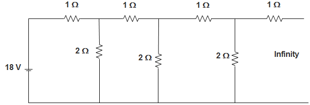
a) 8.18 A
b) 0 A
c) 9 A
d) 10 A
Answer: c
Explanation: Equivalent Resistance, REQ = R = 1 + (2 || R)
Or, REQ = 2
So, I = 182 A = 9 A.
3. In the circuit given below, the phase angle of the current I with respect to the voltage V1 is __________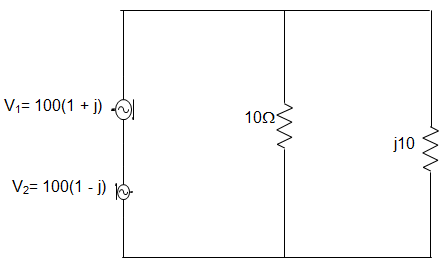
a) 0°
b) +45°
c) -45°
d) -90°
Answer: d
Explanation: Net voltage applied to the circuit is 200∠0° V
I1 = 200∠0°10.0
= 20∠0° = 20
I2 = 200∠0°10∠90°
= 20∠-90° = -j20
I = I1 + I2 = 20(1-j) = 202–√∠45°
Voltage V1 = 100(1+j)
= 1002–√∠45°
∴ Required phase angle = -45° – 45° = -90°.
4. Consider a circuit having 3 identical Ammeters A1, A2, A3 parallel to one another. The 1st Ammeter is in series with a resistance, the 2nd Ammeter is in series with a capacitor and the circuit is excited by a voltage V. If A1 and A3 read 5 and 13 A respectively, reading of A2 will be?
a) 8 A
b) 13 A
c) 18 A
d) 12 A
Answer: d
Explanation: We can infer from the circuit,
A2 = 132–52−−−−−−√
Or, A2 = 169–25−−−−−−√
Or, A2 = 144−−−√
Or, A2 = 12 A.
5. In the circuit given below, the value of V1 is __________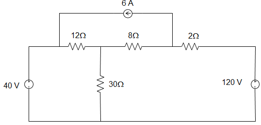
a) 32.2 V
b) -25.23 V
c) 29.25 V
d) -29.25 V
Answer: b
Explanation: VA30+VA−4012+VA−VB8 = 0
Or, 29 VA – 15 VB = 400
Also, VB−VA8+VB−1208 + 6 = 0
Or, VA = 65.23 V, VB = 99.44 V
V1 = 40-65.23 = -25.23 V.
6. For the three coupled coils shown in figure, KVL equation is ____________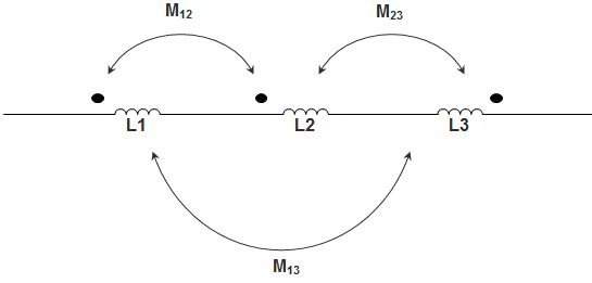
a) V = (L1 + L2 + L3) didt
b) V = (L1 – L2 – L3 – M13) didt
c) V = (L1 + L2 + L3 + 2M12 – 2M23 – 2M13) didt
d) V = (L1 + L2 + L3 – 2M12 + 2M23 + 2M13) didt
Answer: c
Explanation: M12 is positive while M23 and M13 are negative because of dots shown in figure.
So, the KVL equation is given by,
V = (L1 + L2 + L3 + 2M12 – 2M23 – 2M13) didt.
7. A circuit excited by voltage V has a resistance R which is in series with an inductor and capacitor, which are connected in parallel. The voltage across the resistor at the resonant frequency is ___________
a) 0
b) V2
c) V3
d) V
Answer: a
Explanation: Dynamic resistance of the tank circuit, ZDY = LRLC
But given that RL = 0
So, ZDY = L0XC = ∞
Therefore current through circuit, I = V∞ = 0
∴ VD = 0.
8. In the circuit given below, the value of resistance R is _________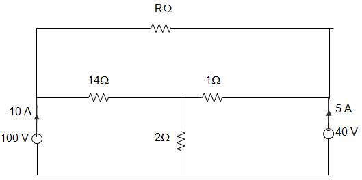
a) 10 Ω
b) 18 Ω
c) 24 Ω
d) 12 Ω
Answer: d
Explanation: Using KVL in loop 1, we get, 100 – 14I – 30 = 0
Or, I = 7014 = 5 A
Then, VP – VQ = 14I – (15-I).1
= 70 – 10 = 60 V
∴ R = 6010−I=605 = 12 Ω.
9. The current flowing through the resistance R in the circuit in the figure has the form 2 cos 4t, where R is ____________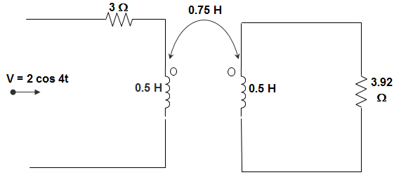
a) (0.18 + j0.72)
b) (0.46 + j1.90)
c) – (0.18 + j1.90)
d) (0.23 – 0.35 j)
Answer: d
Explanation: Inductor is not given, hence ignoring the inductance. Let I1 and I2 are currents in the loop then,
I1 = 2cos4t3
= 0.66 cos 4t
Again, I2 = −jX4X0.75I13.92−2.56j
= (0.23 – 0.35j) cos 4t
10. In the circuit given below, the voltage VAB is _________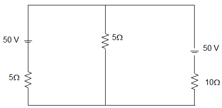
a) 6 V
b) 25 V
c) 10 V
d) 40 V
Answer: a
Explanation: For finding the Thevenin Equivalent circuit across A-B we remove the 5 Ω resistor.
Then, I = 10+5015 = 4 A
VOC = 50 – (10×4) =10 V
And REQ = 10×510+5=103 Ω
Current I1 = 1010/3+5=65
Hence, VAB = 65×5 = 6 V.
11. In the circuit given below, the magnitudes of VL and VC are twice that of VK. Calculate the inductance of the coil, given that f = 50.50 Hz.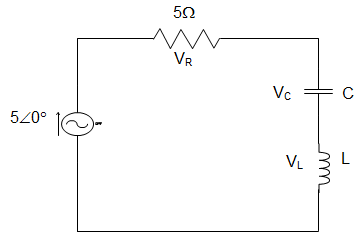
a) 6.41 mH
b) 5.30 mH
c) 3.18 mH
d) 2.31 mH
Answer: c
Explanation: VL = VC = 2 VR
∴ Q = VLVR = 2
But we know, Q = ωLR=1ωCR
∴ 2 = 2πf×L5
Or, L = 3.18 mH.
12. In the circuit given below, the current source is 1 A, voltage source is 5 V, R1 = R2 = R3 = 1 Ω, L1 = L2 = L3 = 1 H, C1 = C2 = 1 F. The current through R3 is _________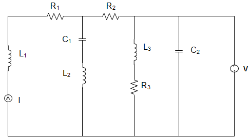
a) 1 A
b) 5 A
c) 6 A
d) 8 A
Answer: b
Explanation: At steady state, the circuit becomes,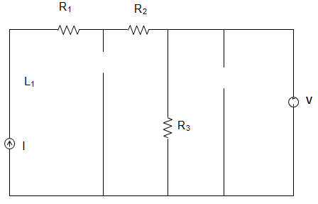
∴ The current through R3 = 51 = 5 A.
13. In the circuit given below, the capacitor is initially having a charge of 10 C. 1 second after the switch is closed, the current in the circuit is ________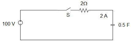
a) 14.7 A
b) 18.5 A
c) 40.0 A
d) 50.0 A
Answer: a
Explanation: Using KVL, 100 = Rdqdt+qC
100 C = RCdqdt + q
Or, ∫qqodq100C−q=1RC∫t0dt
100C – q = (100C – qo)e-t/RC
I = dqdt=(100C–qo)RCe−1/1
∴ e-t/RC = 40e-1 = 14.7 A.
14. A circuit is given in the figure below. The Norton equivalent as viewed from terminals x and x’ is ___________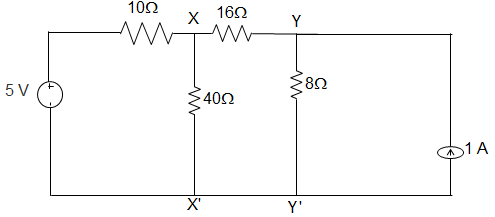
a) 6 Ω and 1.333 A
b) 6 Ω and 0.833 A
c) 32 Ω and 0.156 A
d) 32 Ω and 0.25 A
Answer: b
Explanation: We, draw the Norton equivalent of the left side of xx’ and source transformed right side of yy’.
Vxx’ = VN = 48+82418+124 = 5V
∴ RN = 8 || (16 + 8)
= 8×248+24 = 6 Ω
∴ IN = VNRN=56 = 0.833 A.
15. In the circuit given below, the current source is 1 A, voltage source is 5 V, R1 = R2 = R3 = 1 Ω, L1 = L2 = L3 = 1 H, C1 = C2 = 1 F. The current through the voltage source V is _________
a) 1 A
b) 3 A
c) 2 A
d) 4 A
Answer: d
Explanation: At steady state, the circuit becomes,
∴ The current through the voltage source V = 5 – 1 = 4 A.
Advanced Problems Involving Complex Circuit Diagram – 2
1. In the circuit given below, the KVL for first loop is ___________
a) V (t) = R1i1 + L1 di1dt + M di2dt
b) V (t) = R1i1 – L1 di1dt – M di2dt
c) V (t) = R1i1 + L1 di1dt – M di2dt
d) V (t) = R1i1 – L1 di1dt + M di2dt
Answer: c
Explanation: We know that, in general, the KVL is of the form V (t) = R1i1 + L1 di1dt + M di2dt
But here, M term is negative because i1, is entering the dotted terminal and i2, is leaving the dotted terminal.
So, V (t) = R1i1 + L1 di1dt – M di2dt.
2. In a parallel RL circuit, 12 A current enters into the resistor R and 16 A current enters into the Inductor L. The total current I the sinusoidal source is ___________
a) 25 A
b) 4 A
c) 20 A
d) Cannot be determined
Answer: c
Explanation: Currents in resistance and inductance are out of phase by 90°.
Hence, I = I21+I22
Or, I = [122 + 162]0.5
Or, I = 144+256−−−−−−−−√=400−−−√
= 20 A.
3. Consider a series RLC circuit having resistance = 1Ω, capacitance = 1 F, considering that the capacitor gets charged to 10 V. At t = 0 the switch is closed so that i = e-2t. When i = 0.37 A, the voltage across capacitor is _____________
a) 1 V
b) 6.7 V
c) 0.37 V
d) 0.185 V
Answer: b
Explanation: We know that, during discharge of capacitor,
VC = VR
Now, VR = 0.67 X 10 = 6.7 V
So, VC = 6.7 V.
4. A waveform is of the form of a trapezium, which increases linearly with the linear slope till θ = π3, constant till θ = π2 and again linearly decreases to 0 till θ = π. The average value of this waveform is ______________
a) 2 V
b) 0 V
c) 4 V
d) 3 V
Answer: d
Explanation: The average value of the waveform = 2XAreaof1sttriangle+Areaof2ndtriangleπ
= 2Xπ3X12X6+6(π2–π3)π
= 2π+ππ = 3 Volt.
5. For a series RLC circuit excited by a unit step voltage, Vc is __________
a) 1 – e-t/RC
b) e-t/RC
c) et/RC
d) 1
Answer: a
Explanation: At t = 0, Vc = 0 and at t = ∞, Vc = 1.
This condition can be satisfied only by (1 – e-t/RC).
6. In the circuit given below, a dc circuit fed by a current source. With respect to terminals AB, Thevenin’s voltage and Thevenin’s resistance are ____________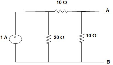
a) VTH = 5 V, RTH = 0.75 Ω
b) VTH = 0.5 V, RTH = 0.75 Ω
c) VTH = 2.5 V, RTH = 1 Ω
d) VTH = 5 V, RTH = 1 Ω
Answer: b
Explanation: VTH = 1X2040 X 1 = 0.5 V
Also, RTH = 1X3040 = 0.75 Ω.
7. In the circuit given below, the value of R is ____________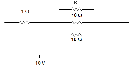
a) 12 Ω
b) 6 Ω
c) 3 Ω
d) 1.5 Ω
Answer: b
Explanation: The resistance of parallel combination is given by,
Req = 403 – 10 = 3.33 Ω
Or, 13.33=112+115+115
Or, R = 6 Ω.
8. A circuit consists of an excitation voltage VS, a resistor network and a resistor R. For different values of R, the values of V and I are as given, R = ∞, V = 5 volt; R = 0, I = 2.5 A; when R = 3 Ω, the value of V is __________
a) 1 V
b) 2 V
c) 3 V
d) 5 V
Answer: c
Explanation: When R = ∞, V = 5v,
Then, Voc = 5V and the circuit is open
When R = 0, I = 2.5A
Then, Isc = 2.5 and the circuit is short circuited.
So, Req = VOCISC
= 52.5 = 2 Ω
Hence the voltage across 3 Ω is 3 volt.
9. Three inductors each 30 mH are connected in delta. The value of inductance or each arm of equivalent star is _____________
a) 10 mH
b) 15 mH
c) 30 mH
d) 90 mH
Answer: a
Explanation: We know that if an inductor L is connected in delta, then the equivalent star of each arm = LXLL+L+L
Given that, L = 30 mH
= 30X3030+30+30
= 90090 = 10 mH.
10. In a series RLC circuit having resistance R = 2 Ω, and excited by voltage V = 1 V, the average power is 250 mW. The phase angle between voltage and current is ___________
a) 75°
b) 60°
c) 15°
d) 45°
Answer: d
Explanation: VI cos θ = 0.25 or I cos θ = 0.25
Or, Z cosθ = 2
Or, VI cosθ = 2
Or, cos θ = 12√
So, from the above equations, cos θ = 0.707 and θ = 45°.
11. In the circuit given below, the equivalent capacitance is _________________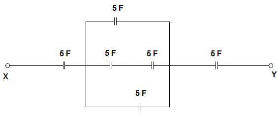
a) 1.6 F
b) 3.1 F
c) 0.5 F
d) 4.6 F
Answer: b
Explanation: CCB = (C2C3C2+C3) + C5 = 7.5 F
Now, CAB = (C1CCBC1+CCB) + C6 = 8 F
CXY = CAB×C4CAB+C4 = 3.1 F.
12. In the circuit given below, the equivalent capacitance is ______________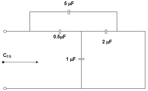
a) 5.43 μF
b) 4.23 μF
c) 3.65 μF
d) 5.50 μF
Answer: a
Explanation: The 2 μF capacitor is in parallel with 1 μF capacitor and this combination is in series with 0.5 μF.
Hence, C1 = 0.5(2+1)0.5+2+1
= 1.53.5 = 0.43
Now, C1 is in parallel with the 5 μF capacitor.
∴ CEQ = 0.43 + 5 = 5.43 μF.
13. In the circuit given below, the voltage across AB is _______________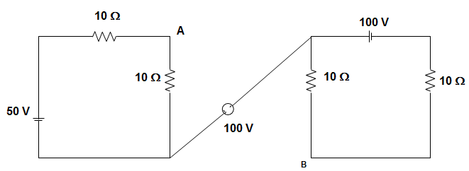
a) 250 V
b) 150 V
c) 325 V
d) 100 V
Answer: c
Explanation: Loop current I1 = 5020 = 2.5 A
I2 = 10020 = 5 A
VAB = (50) (2.5) + 100 + (5) (20)
= 125 + 100 + 100
= 325 V.
14. The number of non-planar graph of independent loop equations is ______________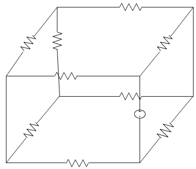
a) 8
b) 12
c) 3
d) 5
Answer: c
Explanation: The total number of independent loop equations are given by L = B – N + 1 where,
L = number of loop equations
B = number of branches = 10
N = number of nodes = 8
∴ L = 10 – 8 + 1 = 3.
15. In the circuit given below, M = 20. The resonant frequency is _______________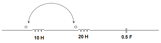
a) 4.1 Hz
b) 41 Hz
c) 0.41 Hz
d) 0.041 Hz
Answer: d
Explanation: IEQ = L1 + L2 + 2M
LEQ = 10 + 20 + 2 × 120 = 30.1 H
∴ FO = 12πLC√
= 12π30.1×0.5√
= 0.041 Hz.