Single Phase Series Circuits MCQs ( Electrical Engineering ) MCQs – Electrical Engineering MCQs

Latest Electrical Engineering MCQs
By practicing these MCQs of Single Phase Series Circuits MCQs ( Electrical Engineering ) MCQs – Latest Competitive MCQs , an individual for exams performs better than before. This post comprising of objective questions and answers related to “Single Phase Series Circuits MCQs ( Electrical Engineering ) Mcqs “. As wise people believe “Perfect Practice make a Man Perfect”. It is therefore practice these mcqs of Electrical Engineeringto approach the success. Tab this page to check “Single Phase Series Circuits MCQs ( Electrical Engineering )” for the preparation of competitive mcqs, FPSC mcqs, PPSC mcqs, SPSC mcqs, KPPSC mcqs, AJKPSC mcqs, BPSC mcqs, NTS mcqs, PTS mcqs, OTS mcqs, Atomic Energy mcqs, Pak Army mcqs, Pak Navy mcqs, CTS mcqs, ETEA mcqs and others.
Single Phase Series Circuits MCQs ( Electrical Engineering ) MCQs – Electrical Engineering MCQs
The most occurred mcqs of Single Phase Series Circuits MCQs ( Electrical Engineering ) in past papers. Past papers of Single Phase Series Circuits MCQs ( Electrical Engineering ) Mcqs. Past papers of Single Phase Series Circuits MCQs ( Electrical Engineering ) Mcqs . Mcqs are the necessary part of any competitive / job related exams. The Mcqs having specific numbers in any written test. It is therefore everyone have to learn / remember the related Single Phase Series Circuits MCQs ( Electrical Engineering ) Mcqs. The Important series of Single Phase Series Circuits MCQs ( Electrical Engineering ) Mcqs are given below:
Alternating Current in a Resistive & Inductive Circuit
1. Instantaneous voltage is the product of resistance and _____________ current in a resistive circuit.
a) Instantaneous
b) Average
c) RMS
d) Peak
Answer: a
Explanation: V=IR. So, V(t)=i(t)R
Instantaneous voltage is the product of resistance and instantaneous current in a resistive circuit.
2. Find the value of the instantaneous voltage if the resistance is 2 ohm and the instantaneous current in the circuit is 5A.
a) 5V
b) 2V
c) 10V
d) 2.5V
Answer: c
Explanation: We know that,
v=iR, substituting the given values from the question, we get v=10V.
3. The power for a purely resistive circuit is zero when?
a) Current is zero
b) Voltage is zero
c) Both current and voltage are zero
d) Either current or voltage is zero
Answer: d
Explanation: P=VIcosϕ Power in a circuit is the product of voltage, current and the cosine of the phase angle. Phase angle is 00 for purely resistive circuit so, P=VI. Hence if either voltage or current is zero, the power is zero.
4. The correct expression for the instantaneous current if instantaneous voltage is Vm(sint) in a resistive circuit is?
a) 1A
b) 2A
c) 3A
d) 4A
Answer: b
Explanation: We know that:V=Vm(sint)
Since i=V/R, we can write, i=Vm(sint)/R.
5. Calculate the resistance in the circuit if the rms voltage is 20V and the rms current is 2A.
a) 2 ohm
b) 5 ohm
c) 10 ohm
d) 20 ohm
Answer: c
Explanation: We know that:
R=V/I
Substituting the given values from the question, we get R=10 ohm.
6. The correct expression for the instantaneous current in a resistive circuit is?
a) i=Vm(sint)/R
b) i=Vm(cost)/R
c) i=V(sint)/R
d) i=V(cost)/R
Answer: a
Explanation: The instantaneous voltage can be written in terms of the maximum voltage in the following manner:
v=Vm(sint)
Since i=v/R, we can write, i=Vm(sint)/R.
7. Can ohm’s law be applied in an ac circuit?
a) Yes
b) No
c) Depends on the rms current
d) Depends on the rms voltage
Answer: a
Explanation: Ohm’s law can be applied in ac as well as dc circuits. It can be applied in ac circuits because the condition V=IR holds true even in ac circuits.
8. The correct expression for the instantaneous current if instantaneous voltage is Vm(sint) in an inductive circuit is?
a) i = Vm(sint)/XL
b) i = Vm(cost)/XL
c) i = -Vm(sint)/XL
d) i = -Vm(cost)/XL
Answer: d
Explanation: V=Vm*sint
I=V/XL = -Vm(cost)/XL (since current lags voltage by 900 in inductive circuit).
Mechanical Analogy, Current and Voltage in an Inductive Circuit
1. Inductor does not allow sudden changes in?
a) Voltage
b) Current
c) Resistance
d) Inductance
Answer: b
Explanation: The inductor does not allow sudden changes in current because if current changes in the inductor occur in zero time, the voltage becomes zero which is not possible.
2. Inductance is _____________________ to number of turns in the coil.
a) directly proportional
b) inversely proportional
c) equal
d) not related
Answer: a
Explanation: L=µ0N2A/l
Inductance is directly proportional to number of turns in the coil.
3. Choke involve use of _____________
a) Resistor
b) Capacitor
c) Inductor
d) Transistor
Answer: c
Explanation: Choke is a type of coil so it involves use of inductor. Capacitors cannot be used in choke coil.
4. What is the value of current in an inductive circuit when there is no applied voltage?
a) Minimum
b) Maximum
c) Zero
d) Cannot be determined
Answer: b
Explanation: The current in an inductive circuit is maximum when there is no voltage applied because the coils of the inductor store electric flux.
5. What is the current in an inductive circuit when the applied voltage is maximum?
a) Infinity
b) Maximum
c) Zero
d) Cannot be determined
Answer: c
Explanation: The current in an inductive circuit is zero or minimum when the value of the applied voltage is maximum.
6. In an inductive circuit, the voltage_______ the current?
a) Leads
b) Lags
c) Is greater than
d) Is less than
Answer: a
Explanation: In a pure inductive circuit the voltage leads the current and the current lags the voltage by a phase difference of 90 degrees.
7. In an inductive circuit, the current________ the voltage?
a) Leads
b) Lags
c) Is greater than
d) Is less than
Answer: b
Explanation: In a pure inductive circuit the voltage leads the current and the current lags the voltage by a phase difference of 90 degrees.
8. In which device inductor cannot be used?
a) filter circuit
b) transformer
c) choke
d) dielectric
Answer: d
Explanation: Inductor has wide number of applications.
It is used in LR filter circuits, transformer and choke coil.
Resistance and Inductance in Series
1. A resistance of 7 ohm is connected in series with an inductance of 31.8mH. The circuit is connected to a 100V 50Hz sinusoidal supply. Calculate the current in the circuit.
a) 2.2A
b) 4.2A
c) 6.2A
d) 8.2A
Answer: d
Explanation: XL=2*π*f*L = 10 ohm. Z2=(R2+XL2)
Therefore the total impedance Z = 12.2ohm.
V=IZ, therefore I=V/Z=100/12.2 = 8.2A.
2. A resistance of 7 ohm is connected in series with an inductance of 31.8mH. The circuit is connected to a 100V 50Hz sinusoidal supply. Calculate the phase difference.
a) -55.1
b) 55.1
c) 66.1
d) -66.1
Answer: a
Explanation: φ=tan-1(XL/R)=55.1
Since this is an inductive circuit, the current will lag, hence φ= -55.1.
3. A resistance of 7 ohm is connected in series with an inductance of 31.8mH. The circuit is connected to a 100V 50Hz sinusoidal supply. Calculate the voltage across the resistor.
a) 31.8V
b) 57.4V
c) 67.3V
d) 78.2V
Answer: b
Explanation: XL=2*π*f*L = 10 ohm. Z2=(R2+XL2)
Therefore, the total impedance Z = 12.2ohm.
V=IZ, therefore I=V/Z=100/12.2 = 8.2A. Voltage across resistor = 8.2*7 = 57.4V.
4. A resistance of 7 ohm is connected in series with an inductance of 31.8mH. The circuit is connected to a 100V 50Hz sinusoidal supply. Calculate the voltage across the inductor.
a) 52V
b) 82V
c) 65V
d) 76V
Answer: b
Explanation: XL=2*π*f*L = 10 ohm. Z2=(R2+XL2)
Therefore, the total impedance Z = 12.2ohm.
V=IZ, therefore I=V/Z=100/12.2 = 8.2A. Voltage across inductor = 8.2*10 = 82V.
5. A resistance of 7 ohm is connected in series with an inductance of 31.8mH. The circuit is connected to a x V 50Hz sinusoidal supply. The current in the circuit is 8.2A. Calculate the value of x.
a) 10V
b) 50V
c) 100V
d) 120V
Answer: c
Explanation: XL=2*π*f*L= 10 ohm. Z2=(R2+XL2)
Therefore, the total impedance Z = 12.2ohm.
V=IZ, therefore V = 12.2*8.2 = 100V.
6. Which, among the following, is the correct expression for φ.
a) φ=tan-1 (XL/R)
b) φ=tan-1 (R/XL)
c) φ=tan-1 (XL*R)
d) φ=cos-1 (XL/R)
Answer: a
Explanation: From the impedance triangle, we get tanφ= XL/R.
Hence φ=tan-1 (XL/R).
7. For an RL circuit, the phase angle is always ________
a) Positive
b) Negative
c) 0
d) 90
Answer: b
Explanation: For a series resistance and inductance circuit the phase angle is always a negative value because the current will always lag the voltage.
Inductance In A DC Circuit MCQs
8. What is φ in terms of voltage?
a) φ=cos-1V/VR
b) φ=cos-1V*VR
c) φ=cos-1VR/V
d) φ=tan-1V/VR
Answer: c
Explanation: From the voltage triangle, we get cosφ= VR/V.
Hence φ=cos-1VR/V.
9. What is sinϕ from impedance triangle?
a) XL/R
b) XL/Z
c) R/Z
d) Z/R
Answer: b
Explanation: In Impedance triangle, Base is R, Hypotenuse is Z, Height is XL.
So, sinϕ = XL/Z.
Alternating Current in a Capacitive Circuit
1. What is the resonance frequency of ac circuit?
a) 1/√LC
b) √(L/C)
c) √LC
d) LC
Answer: a
Explanation: At resonance, XL=XC
ωL=1/ωC
ω=1/√LC.
2. What is impedance at resonance?
a) maximum
b) minimum
c) zero
d) cannot be determined
Answer: b
Explanation: At resonance, XL=XC
Z2=R2+(XL-XC)2
Z=R So Z is minimum at resonance.
3. What is the value of impedance at resonance?
a) XL
b) XC
c) R
d) 0
Answer: c
Explanation: At resonance, XL=XC
Z2=R2+(XL-XC)2
Z=R So Z is minimum at resonance.
4. What is φ in terms of voltage?
a) φ=cos-1V/VR
b) φ=cos-1V*VR
c) φ=cos-1VR/V
d) φ=tan-1V/VR
Answer: c
Explanation: Form the voltage triangle, we get cosφ= VR/V.
Hence φ=cos-1VR/V.
5. What is tanϕ for RC circuit?
a) XC/R
b) XL/R
c) R/Z
d) Z/R
Answer: a
Explanation: From the impedance triangle, height gives capacitive reactance and base gives resistance.
tanϕ=XC/R.
6. What is the resonance condition?
a) When XL>XC
b) When XL<XC
c) When XL=XC
d) When XC=infinity
Answer: c
Explanation: The current is in phase with the voltage when the capacitive reactance is in equal to the inductive reactance. This is known as resonance condition.
7. What is the frequency in resonance condition?
a) Minimum
b) Maximum
c) Cannot be determined
d) Zero
Answer: b
Explanation: At resonance condition, the frequency is maximum since the inductive reactance is equal to the capacitive reactance. XL=XC.
Current and Voltage in a Capacitive Circuit
1. Can capacitor fully charge using alternating current?
a) yes
b) no
c) may or may not
d) depend on value of capacitance
Answer: a
Explanation: No, the capacitor cannot be fully charged using alternating current because as soon as the capacitor charges, the alternating current reverses its polarity thereby discharging it.
2. What is the resistance offered by a capacitor?
a) Susceptance
b) Conductance
c) Admittance
d) Reactance
Answer: d
Explanation: Resistance offered to alternating current by inductor or capacitor is known as reactance which is equivalent to resistance of resistor.
3. The combination of resistance and reactance known as ___________
a) Susceptance
b) Impedance
c) Conductance
d) Admittance
Answer: b
Explanation: The combination of resistance and reactance is known as impedance. It is equivalent resistance of an RLC alternating circuit.
4. What is the relation between reactance, resistance and impedance?
a) Z=R+jX
b) Z=R+X
c) Z=R-X
d) Z=R-jX
Answer: a
Explanation: The combination of resistance and reactance is known as impedance. Z=R+jX
Where Z is impedance, R is resistance and X is reactance.
5. What is the real part of the impedance of RLC circuit?
a) Resistance
b) Conductance
c) Admittance
d) Reactance
Answer: a
Explanation: The combination of resistance and reactance is known as impedance. Z=R+jX where Z is impedance, R is resistance and X is reactance. R is real part of Z.
6. What is imaginary part of the impedance of RLC circuit?
a) Resistance
b) Conductance
c) Admittance
d) Reactance
Answer: d
Explanation: The combination of resistance and reactance is known as impedance. Z=R+jX where Z is impedance, R is resistance and X is reactance. X is imaginary part of Z.
7. Which type of current can be stored in a capacitor?
a) Alternating current
b) Direct current
c) Both alternating current and direct current
d) Neither alternating current nor direct current
Answer: b
Explanation: Only direct current can be stored in the capacitor. Capacitor cannot be fully charged using alternating current because as soon as the capacitor charges, alternating current reverses its polarity thereby discharging it. So, we cannot store ac current in capacitor.
Resistance and Capacitance in Series
1. If in an alternating current circuit, resistance is 5 ohm, capacitive reactance is 12 ohm, what is the impedance?
a) 5 ohm
b) 10 ohm
c) 12 ohm
d) 13 ohm
Answer: d
Explanation: R=5Ω, XC=12Ω
Z2=R2+XC2 Substituting the values we get,
Z2 = 52 + 122
Z2 = 169
Z=13 Ω.
2. If in an alternating current circuit, impedance is 26 ohm, capacitive reactance is 24 ohm, what is the resistance?
a) 25 ohm
b) 10 ohm
c) 12 ohm
d) 23 ohm
Answer: b
Explanation: Z=26Ω, XC=24Ω
Z2=R2+XC2 Substituting the values we get,
262 = R2 + 242
676 = R2 + 576
R2 = 100
R=10 Ω.
Alternating Voltage And Current MCQs
3. If in an alternating current circuit, capacitance of 30 µF is connected to a supply of 200V,50Hz. Find the current in the circuit.
a) 1.38 A
b) 1.89 A
c) 1.74 A
d) 0.89 A
Answer: a
Explanation: XC=1/(2πfC)=106.1
I=V/XC=200/106.1=1.89 A.
4. If in an alternating current circuit, capacitance C is connected to a supply of 200V,50Hz. Current in the circuit is 1.89 A. Find the capacitance C.
a) 30 µF
b) 20 µF
c) 10 µF
d) 15 µF
Answer: a
Explanation: XC= V/I = 200/1.89 = 106.1 Ω. XC=1/(2πfC) Substituting the values we get C = 30 µF.
5. In ac circuit, resistance 5 ohm is connected with capacitor having capacitive reactance 12 ohm. Supply of 260 V is connected to the circuit. Calculate the current in the circuit.
a) 40 A
b) 10 A
c) 20 A
d) 30 A
Answer: c
Explanation: Z2=R2+XC2 Substituting the values we get Z2 = 52 + 122
Z2 = 169
Z=13 Ω.
I=V/Z = 260/13=20 A.
6. In ac circuit, resistance 5 ohm is connected with capacitor having capacitive reactance 12 ohm. Supply of 260 V is connected to the circuit. Calculate the voltage across resistance.
a) 300 V
b) 200 V
c) 240 V
d) 100 V
Answer: d
Explanation: Z2=R2+XC2 Substituting the values we get
Z2 = 52 + 122
Z2 = 169
Z=13 Ω.
I = V/Z = 260/13=20 A.
VR=iR=20*5=100 V.
7. In ac circuit, resistance 5 ohm is connected with a capacitor having capacitive reactance 12 ohm. Supply of 260 V is connected to the circuit. Calculate the voltage across a capacitor.
a) 300 V
b) 200 V
c) 240 V
d) 100 V
Answer: c
Explanation: Z2=R2+XC2 Substituting the values we get
Z2 = 52 + 122
Z2 = 169
Z=13 Ω.
I = V/Z = 260/13=20 A.
VC=iXC=20*12=240 V.
Alternating Current in an RLC Circuit
1. Find the total voltage applied in a series RLC circuit when i=3mA, VL=30V, VC=18V and R=1000 ohms.
a) 3.95V
b) 51V
c) 32.67V
d) 6.67V
Answer: b
Explanation: Total voltage= VR+VL+VC.
VR=1000*3*10-3=3V. Therefore, total voltage = 30+18+3=51V.
2. In an RLC circuit, which of the following is always used as a vector reference?
a) Voltage
b) Resistance
c) Impedance
d) Current
Answer: a
Explanation: In an RLC circuit, the voltage is always used as a reference and according to the phase of the voltage, the phase of the other parameters is decided.
3. In an RLC circuit, the power factor is always ____________
a) Positive
b) Negative
c) Depends on the circuit
d) Zero
Answer: c
Explanation: In an RLC series circuit, the power factor depends on the number of resistors and inductors in the circuit, hence it depends on the circuit.
4. In an RLC series phasor, we start drawing the phasor from which quantity?
a) Voltage
b) Resistance
c) Impedance
d) Current
Answer: d
Explanation: In an RLC series phasor diagram, we start drawing the phasor from the quantity which is common to all three components, that is the current.
5. What is the correct expression for the phase angle in an RLC series circuit?
a) φ=tan-1(XL-XC)/R
b) φ=tan-1 (XL+XC)/R
c) φ=tan(XL-XC)/R
d) φ=tan-1 (XL-XC)
Answer: a
Explanation: from the impedance triangle we get tanφ=(XL-XC)/R.
Hence φ=tan-1 (XL-XC)/R.
6. When is tanφ positive?
a) When inductive reactance is less than capacitive reactance
b) When inductive reactance is greater than capacitive reactance
c) When inductive reactance is equal to capacitive reactance
d) When inductive reactance is zero
Answer: b
Explanation: tanφ is positive when inductive reactance is greater than capacitive reactance because current will lag the voltage.
7. When is tanφ negative?
a) When inductive reactance is less than capacitive reactance
b) When inductive reactance is greater than capacitive reactance
c) When inductive reactance is equal to capacitive reactance
d) When inductive reactance is zero
Answer: a
Explanation: tanφ is negative when inductive reactance is less than capacitive reactance because current will lead the voltage.
8. Which of the following is not ac waveform?
a) sinusoidal
b) square
c) constant
d) triangular
Answer: c
Explanation: AC waveforms are those which periodically changes polarity with time. Sinusoidal wave, square wave, triangular wave change their polarity at regular intervals so they are ac waveforms. Constant wave does not change its polarity so it is not an ac waveform.
9. What is not a frequency for ac current?
a) 50 Hz
b) 55 Hz
c) 0Hz
d) 60 Hz
Answer: c
Explanation: DC current is a type of constant current so it has frequency of zero hertz. So, AC current can have rest other frequencies other than zero.
10. Which type of ac waveform is given in figure?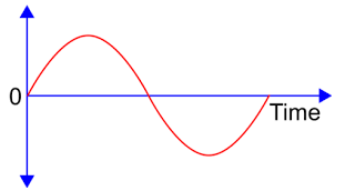
a) sinusoidal
b) triangular
c) square
d) complex waveform
Answer: a
Explanation: The figure depicts ac waveform of sinusoidal nature changing its polarity after regular intervals sinusoidally.