Up To Date Electric Circuits MCQs – Simple Resistive Circuits MCQs ( Electric Circuits ) MCQs

Latest Electric Circuits MCQs
By practicing these MCQs of Simple Resistive Circuits MCQs ( Electric Circuits ) MCQs – Latest Competitive MCQs , an individual for exams performs better than before. This post comprising of objective questions and answers related to “Simple Resistive Circuits MCQs ( Electric Circuits ) Mcqs “. As wise people believe “Perfect Practice make a Man Perfect”. It is therefore practice these mcqs of Electric Circuitsto approach the success. Tab this page to check “Simple Resistive Circuits MCQs ( Electric Circuits )” for the preparation of competitive mcqs, FPSC mcqs, PPSC mcqs, SPSC mcqs, KPPSC mcqs, AJKPSC mcqs, BPSC mcqs, NTS mcqs, PTS mcqs, OTS mcqs, Atomic Energy mcqs, Pak Army mcqs, Pak Navy mcqs, CTS mcqs, ETEA mcqs and others.
Simple Resistive Circuits MCQs ( Electric Circuits ) MCQs – Electric Circuits MCQs
The most occurred mcqs of Simple Resistive Circuits MCQs ( Electric Circuits ) in past papers. Past papers of Simple Resistive Circuits MCQs ( Electric Circuits ) Mcqs. Past papers of Simple Resistive Circuits MCQs ( Electric Circuits ) Mcqs . Mcqs are the necessary part of any competitive / job related exams. The Mcqs having specific numbers in any written test. It is therefore everyone have to learn / remember the related Simple Resistive Circuits MCQs ( Electric Circuits ) Mcqs. The Important series of Simple Resistive Circuits MCQs ( Electric Circuits ) Mcqs are given below:
The Voltage Divider and Current Divider Circuits
1. Where voltage division problem arises
a) Series connected resistors
b) Parallel connected resistors
c) When resistors are equal
d) Both series and parallel resistors.
Answer: a
Explanation: In series, voltage is the difference and current same.
2. Where current division problem arises
a) Series connected resistors
b) Parallel connected resistors
c) When resistors are equal
d) Both series and parallel resistors.
Answer: b
Explanation: In parallel voltage is same and current is the difference.
3. If there are 3 Resistors R1, R2 and R3 in series and V is total voltage and I is total current then Voltage across R2 is
a) V R3/ R1 + R2 + R3
b) V R2/ R1 + R2 + R3
c) V R1/R1 + R2 + R3
d) V
Answer: b
Explanation: V2 =I R2
= V R2/ R1 + R2 + R3.
4.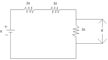
Calculate Voltage across 2Ω Resistor where supply v= 10volts.
a) 2V
b) 3V
c) 10V
d) 4V
Answer: d
Explanation: I = 10/5 = 2A
V2 = 10(2)
V2 = I.R2
= 2(2)
4V.
5.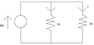
Calculate i =?
a) -1A
b) +2A
c) 8A
d) -5A
Answer: b
Explanation: i = 1/1+3(8)
= 2A.
6. For a parallel connected resistor R1, R2 and a voltage of V volts. Current across the first resistor is given by
a) I R1
b) I R2
c) I R1 / R1 + R2
d) I R2 / R1 + R2
Answer: d
Explanation: I1 = V / R1
R = R1. R2 / R1 + R2
= I . R1. R2 / R1 . R1 + R2
I1 = I R2 / R1 + R2.
7. R1 = 1Ω, R2 = 3Ω, R3 = 5Ω and R4 = 7Ω connected in series. Total voltage = 20V, Current I, V2 =?
a) I = 1.23, V2 = 3.75
b) I = 1.25, V2 = 3.75
c) I = 1.15, V2= 3.73
d) I = 1.16, V2 = 3.72
Answer: b
Explanation: I = 20/ 1 + 3 + 5 + 7 = 1.25A
V2 = V. R2 / R1 + R2 + R3 + R4
= 20(3)/16
= 3.75V.
8. R1 = 1Ω, R2 = 3Ω, R3 = 5Ω and R4 = 7Ω connected in parallel. Total Current = 23A. Then V, I1 , I2 =?
a) 12.26v, 1.725, 2.875
b) 12.23v, 2.875, 1.725
c) 11.26v, 1.95, 1.74
d) 11.23v, 1.74, 1.95
Answer: a
Explanation: V = I/R
V = I (R1 + R2) R1 R2 = 12.26v
I1 = IR2/ R1 + R2 = 1.725A
I2 = IR1/ R1 + R2
= 2.875A.
9. Voltage division is necessary for parallel resistance networks
a) True
b) False
Answer: b
Explanation: In parallel, connection voltage is same so no division is required.
10. Why is current division necessary?
a) In series current is the same
b) In parallel current differs
c) Because the voltage is also different
d) Because of Kirchhoff’s laws.
Answer: b
Explanation: In parallel current differs.
Measuring Voltage and Current
1. ____________ helps in current measurement by placing it in ____________ with the circuit element.
a) Voltmeter, Parallel
b) Ammeter, series
c) Voltmeter, series
d) Ammeter, parallel
Answer: b
Explanation: In series, current is same. So Ammeter is placed in series and is used to measure current.
2. An ideal voltmeter has ___________ equivalent resistance and ideal ammeter has ___________ equivalent resistance.
a) Unity, Unity
b) Zero, infinite
c) Infinite, Zero
d) Zero, Zero
Answer: c
Explanation: An ideal voltmeter has Infinite equivalent resistance and ideal ammeter has zero equivalent resistance.
3. Continuous voltages (or) current signals are measured using
a) Tachometers
b) Sonometers
c) Analog meters
d) Digital meters
Answer: d
Explanation: Digital meters are used to measure current (or) voltage signals at discrete points in time known as sampling times.
4. Digital meters are preferable than analog meters.
a) True
b) False
Answer: a
Explanation: Features like easy connection, Introduction of less resistance into the circuit to which they all connected and also due to read out mechanism digital meter are preferred.
5. A 20mv, 1mA d’Arsonval movement is used in an ammeter whose full-scale reading is 10 mA. Determine RA.
a) 2.222Ω
b) 6.667Ω
c) 5.92Ω
d) 3.333Ω
Answer: a
Explanation: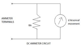
1 mA flowing through coil implies that 9mA must be diverted through RA.
V = ir
20 * 10-3 = 9 * 10-3 RA
RA= 2.222Ω.
6. A 25mv, 2mA d’Arsonval movement is to be used in voltmeter whose full scale reading is 100v. The resistance inserted by 100v meter into circuit is ___________
a) 1 * 105Ω
b) 1 * 106Ω
c) 1 * 104Ω
d) 1 * 103Ω
Answer: a
Explanation: v = iR
R = v/i
= 100/1mA
= 100,000Ω.
Circuit Variables And Elements MCQs
7. An ideal voltmeter functions as __________ circuit
a) A short
b) An open
c) A power
d) An infinite
Answer: b
Explanation: An ideal voltmeter offers an infinite equivalent resistance. So acts as an open circuit.
8. An ideal ammeter functions as __________ circuit
a) A short
b) An open
c) A power
d) An infinite
Answer: a
Explanation: An ideal ammeter offers a zero equivalent resistance. So acts a short circuit.
9. A 100mv, 5mA d’Arsonval movement is to be used in an ammeter whose full-scale reading is 1A. Calculate RA.
a) 0.7 ohms
b) 0.5 ohms
c) 0.1 ohms
d) 0.2 ohms
Answer: c
Explanation: 5mA is flowing through the coil which implies 995mA are diverted through RA.
V = iR
= 100 * 10-3
= 995 * 10-3 RA
RA = 0.100Ω.
10. A 122mv, 12mA d’Arsonval movement is to be used in voltmeter whose full scale reading is 120v. The resistance inserted by 120v _____________
a) 1200Ω
b) 12000Ω
c) 1000Ω
d) 10,000Ω
Answer: d
Explanation: R =120/12 * 10-3
= 10,000Ω.
Measuring Resistance the Wheatstone Bridge and Delta-to-Wye (Pi-to-Tee) Equivalent Circuits
1. The Wheatstone Bridge is mainly used to measure ______________
a) Currents
b) Voltages
c) Node potentials
d) Resistances
Answer: d
Explanation: Resistances can be measured by various methods. Wheatstone bridge is one such method. In this method resistances in the range of 1Ω to 1 MΩ can be measured.
2. The relation between the resistances in the given Wheatstone bridge circuit is _____________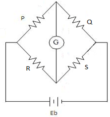
a) P/S = R/Q
b) PR = QS
c) P/Q = R/S
d) PQ = RS
Answer: c
Explanation: The relation is P/Q=R/S or PS=QR.
3. Find the unknown resistance value in given circuit.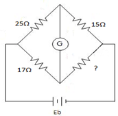
a) 10.2Ω
b) 11.7Ω
c) 10.5Ω
d) 11.5Ω
Answer: a
Explanation: A/B=C/D. Using this D= 10.2Ω.
4. Lower resistances are difficult to measure using Wheatstone bridge circuit because of ____________
a) Leakage currents
b) I2R effects
c) Power dissipation
d) Thermal breakdown
Answer: b
Explanation: A standard Wheatstone bridge couldn’t measure lower resistances because of thermoelectric voltages which are generated at the junctions of the dissimilar metals and also because of thermal heating effects- that is, i2R effects.
5. If P/Q=1, unknown resistance S=1000Ω and R could be varied from 0 to 100Ω then the bridge could be ___________
a) A balanced circuit
b) A rectified circuit
c) An unbalanced circuit
d) An identical circuit
Answer: c
Explanation: P/Q=R/S. If P/Q=1 then according to given range of R and S, the bridge circuit could never be a balanced one.
6. The other name for Delta connection is ___________
a) Star connection
b) Pi connection
c) T connection
d) Y connection
Answer: b
Explanation: Delta connection is also known as Pi connection because the ∆ can be shaped into π without disturbing the electrical equivalence of both the structures.
7. Star connection can also be called as Y (or) T connection.
a) True
b) False
Answer: a
Explanation: Star connection can also be called as Y (or) T connection because the star can be shaped into Y or T without disturbing the electrical equivalence of both the structures.
8. If R2 = RC RA / (RA +RB +RC ) then R3 equals?
a) RA RB / (RA +RB +RC )
b) RC RA / (RA +RB +RC )
c) RB RC / (RA +RB +RC )
d) RX RA / (RA +RB +RC )
Answer: a
Explanation: R3 = RA RB / (RA +RB +RC ).
9. Convert the given Delta circuit to star circuit and give the Ra , Rb and Rc values.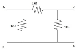
a) Ra=5Ω, Rb = 4.5Ω, Rc=4.67Ω
b) Ra=4Ω, Rb=4.30Ω, Rc=4.66Ω
c) Ra=3Ω, Rb=4Ω, Rc =5Ω
d) Ra=5.2Ω, Rb=4.2Ω, Rc =4.89Ω
Answer: b
Explanation: By using the standard formulae the delta circuit can be converted into star circuit.
10. Find VAB if iAB = 5A.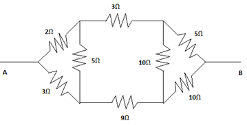
a) 32.76V
b) 35.56V
c) 36.12V
d) 34.21V
Answer: d
Explanation: By converting the star circuits into the delta and then measuring the equivalent resistance, voltage value can be calculated using this resistance and the given current value.
11. Convert the given star network into Pi network and calculate the sum of all the resistances in the obtained Pi network.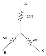
a) 125.5Ω
b) 122.5Ω
c) 127.8Ω
d) 129.8Ω
Answer: b
Explanation: Conversion of given network into delta gives the resistances.
After that sum of the resistances equals 122.5Ω.
12. The star and delta networks would be electrically equal if resistances measured between any pair of terminals __________
a) Is different
b) Greater in star
c) Greater in delta
d) Is equal
Answer: d
Explanation: The star and delta networks would be electrically equal if a resistance measured between any pair of terminals is same.
13. A Wheatstone bridge is balanced when the galvanometer shows __________ reading.
a) 0A
b) 1A
c) Infinity
d) -1A
Answer: a
Explanation: A Wheatstone bridge is balanced when the galvanometer shows 0A reading when resistors obey P/Q=R/S.
14. __________ are difficult to measure using Wheatstone bridge.
a) Higher resistances
b) Currents
c) Lower resistances
d) Voltages
Answer: c
Explanation: Specifically Kelvin Bridge is used for measuring lower resistances.
15. What will be the resistance between B and C when the network given below is converted into delta?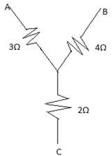
a) 13Ω
b) 8.66Ω
c) 6.5Ω
d) 7.33Ω
Answer: b
Explanation: Resistance between B and C = 2+4+ ((2*4)/3).
Up To Date Electric Circuits MCQs – Simple Resistive Circuits MCQs ( Electric Circuits ) MCQs