Up To Date Filters and Attenuators MCQs ( Network Theory ) MCQs – Network Theory MCQs

Latest Network Theory MCQs
By practicing these MCQs of Filters and Attenuators MCQs ( Network Theory ) MCQs – Latest Competitive MCQs , an individual for exams performs better than before. This post comprising of objective questions and answers related to “ Filters and Attenuators MCQs ( Network Theory ) Mcqs “. As wise people believe “Perfect Practice make a Man Perfect”. It is therefore practice these mcqs of Network Theory to approach the success. Tab this page to check ” Filters and Attenuators MCQs ( Network Theory )” for the preparation of competitive mcqs, FPSC mcqs, PPSC mcqs, SPSC mcqs, KPPSC mcqs, AJKPSC mcqs, BPSC mcqs, NTS mcqs, PTS mcqs, OTS mcqs, Atomic Energy mcqs, Pak Army mcqs, Pak Navy mcqs, CTS mcqs, ETEA mcqs and others.
Network Theory MCQs – Filters and Attenuators MCQs ( Network Theory ) MCQs
The most occurred mcqs of Filters and Attenuators MCQs ( Network Theory ) in past papers. Past papers of Filters and Attenuators MCQs ( Network Theory ) Mcqs. Past papers of Filters and Attenuators MCQs ( Network Theory ) Mcqs . Mcqs are the necessary part of any competitive / job related exams. The Mcqs having specific numbers in any written test. It is therefore everyone have to learn / remember the related Filters and Attenuators MCQs ( Network Theory ) Mcqs. The Important series of Filters and Attenuators MCQs ( Network Theory ) Mcqs are given below:
Inverse Network
1. The impedances Z1 and Z2are said to be inverse if?
a) Z1Z2 = R0
b) Z1 + Z2 = R0
c) 1/Z1 + 1/Z2 = R0
d) Z1Z2 = R02
Answer: d
Explanation: The impedances Z1 and Z2 are said to be inverse if the geometric mean of the two impedances is a real number.
2. An inverse network may be obtained by?
a) Converting each series branch into another series branch
b) Converting each series branch into another parallel branch
c) Converting each parallel branch into another series branch
d) None of the mentioned
Answer: c
Explanation: An inverse network may be obtained by converting each parallel branch into another series branch and vice-versa and not by converting each series branch into another series branch and not by converting each series branch into another parallel branch.
3. An inverse network may be obtained by converting each resistance element R into a corresponding resistive element of value?
a) R02/R
b) R/R02
c) R0/R
d) R/R0
Answer: a
Explanation: To obtain the inverse network we have to convert each resistance element R into a corresponding resistive element of value R02/R.
4. An inverse network may be obtained by converting each inductance L into a capacitance of value?
a) L/R0
b) L/R02
c) R0/L
d) R02/L
Answer: b
Explanation: An inverse network may be obtained by converting each inductance L should be converted into a capacitance of value L/R02 to obtain the inverse network.
5. An inverse network may be obtained by converting each capacitance C into an inductance of value?
a) CR02
b) CR0
c) R02/C
d) C/R02
Answer: a
Explanation: An inverse network is obtained by converting each capacitance C into an inductance of value CR02 where R0 is resistance.
6. Consider the network shown below. Find the value of capacitance C1‘ after converting the inductance L1 into a capacitance.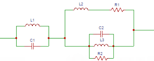
a) R02/L1
b) R0/L1
c) L1/R02
d) L1/R0
Answer: c
Explanation: An inverse network may be obtained by converting Each inductance L should be converted into a capacitance of value L/R02 to obtain the inverse network. The value of capacitance C1‘ after converting the inductance into a capacitance is L1/R02. C1’ = L1/R02.
7. Consider the network shown below, find the value of inductance L1‘ after converting the capacitance into an inductance.
a) C1/R02
b) R02/C1
c) C1R0
d) C1R02
Answer: d
Explanation: An inverse network is obtained by converting each capacitance C into an inductance of value CR02 where R0 is resistance. The value of inductance L1‘ after converting the capacitance into an inductance is L1‘ = C1R02.
8. Consider the network shown below, find the value of resistance R1‘ after converting the resistance R1.
a) R1/R0
b) R0/R1
c) R1/R02
d) R02/R1
Answer: d
Explanation: To obtain the inverse network we have to convert each resistance element R into a corresponding resistive element of value R02/R. The value of resistance R1‘ after converting R1 is R1‘ = R02/R1.
9. The value of the capacitance C2‘ after converting the inductor into the C2‘ in the network shown below.
a) L2/R02
b) L2/R0
c) R02/L2
d) R0/L2
Answer: a
Explanation: An inverse network may be obtained by converting Each inductance L should be converted into a capacitance of value L/R02 to obtain the inverse network. The value of the capacitance C2‘ after converting the inductor into the capacitance is
C2‘ = L2/R02.
10. The value of the inductor L2‘ after converting the capacitor into the L2‘ in the network shown below.
a) R02/C2
b) C2R02
c) C2R0
d) R02/C2
Answer: b
Explanation: An inverse network is obtained by converting each capacitance C into an inductance of value CR02 where R0 is resistance. The value of the inductor L2‘ after converting the capacitor into the inductance is L2‘ = C2R02.
Series Equalizer
1. The value of attenuation D is equal to?
a) log10 (N)
b) 10 log10 (N)
c) 20 log10 (N)
d) 40 log10 (N)
Answer: a
Explanation: The value of attenuation D is equal to log10 (N). Attenuation D = log10 (N) where N is input to output power ratio of the load.
2. The value of N in terms of attenuation D is?
a) antilog(D)
b) antilog(D/10)
c) antilog(D/20)
d) antilog(D/40)
Answer: b
Explanation: The value of N in terms of attenuation D is antilog(D/10). N = antilog(D/10) where D is attenuation in decibels.
3. The input to output power ratio of the load (N) is the ratio of the________ to the __________
a) Maximum power delivered to the load when the equalizer is not present, power delivered to the load when equalizer is present
b) Power delivered to the load when equalizer is present, maximum power delivered to the load when the equalizer is not present
c) Maximum power delivered to the load when the equalizer is present, power delivered to the load when equalizer is not present
d) Power delivered to the load when equalizer is not present, maximum power delivered to the load when the equalizer is present
Answer: a
Explanation: The input to output power ratio of the load (N) is the ratio of the maximum power delivered to the load when the equalizer is not present to the power delivered to the load when equalizer is present.
4. The N is defined as?
a) output power/ input power
b) input power/ output power
c) output power at inductor/ input power
d) output power at capacitor/ input power
Answer: b
Explanation: The N is defined as the ratio of input power to the output power. N = Pi/Pl where Pi is input power and Pl is output power.
5. The expression of input power of a series equalizer is?
a) Vmax2/Ro
b) Vmax2/2Ro
c) Vmax2/3Ro
d) Vmax2/4Ro
Answer: d
Explanation: The expression of input power of a series equalizer is Pi=(Vmax/2Ro)2 Ro=Vmax2/4Ro
6. The expression of current flowing in a series equalizer is?
a) Vmax/√((Ro)2+(X1)2)
b) Vmax/√((2Ro)2+(X1)2)
c) Vmax/√((2Ro)2+(2X1)2)
d) Vmax/√((Ro)2+(2X1)2)
Answer: c
Explanation: When the equalizer is connected, the expression of current flowing in a series equalizer is I1 = Vmax/√((2Ro)2+(2X1)2) where Vmax is voltage applied to the network and Ro is resistance of the load as well as source and 2X1 is the reactance of the equalizer.
7. What is the power at the load of a series equalizer?
a) [Vmax2/(Ro2+X12)]Ro
b) [Vmax2/(2(Ro2+X12))]Ro
c) [Vmax2/(3(Ro2+X12))]Ro
d) [Vmax2/(4(Ro2+X12))]Ro
Answer: d
Explanation: The power at the load of a series equalizer is P=(Vmax/√((2Ro)2+(2X1)2))2 Ro = [Vmax2/(4(Ro2+X12))]Ro.
8. Determine the value of N in the series equalizer.
a) 1+ X12/Ro2
b) X12/Ro2
c) 1+ Ro2/X12
d) Ro2/X12
Answer: a
Explanation: The N is defined as the ratio of input power to the output power.
N=Pi/Pl = (Vmax2/4Ro)/[Vmax2/(4(Ro2+X12))]Ro=1+X12/Ro2.
9. The expression of N in a full series equalizer considering Z1 as inductor and Z2 as capacitor is?
a) Ro2/(ωL1)2
b) 1+ Ro2/(ωL1)2
c) (ω2 L12)/Ro2
d) 1+ (ω2 L12)/Ro2
Answer: d
Explanation: The expression of N in a full series equalizer considering Z1 as inductor and Z2 as capacitor is N = 1 + X12/Ro2 = 1+ (ω2 L12)/Ro2.
10. The expression of N in a full series equalizer considering Z1 as capacitor and Z2 as inductor is?
a) 1+ (ω2 L12)/Ro2
b) (ω2 L12)/Ro2
c) 1+ Ro2/(ωL1)2
d) Ro2/(ωL1)2
Answer: c
Explanation: The expression of N in a full series equalizer considering Z1 as capacitor and Z2 as inductor is N = 1+ Ro2/X22 = 1+Ro2/(ωL1)2.
Shunt Equalizer
1. In the shunt equalizer, the current flowing from the source is?
a) Vmax(2Ro+jX1)/2Ro(Ro+jX1)
b) Vmax(Ro+jX1)/Ro(Ro+jX1)
c) Vmax(Ro+jX1)/2Ro(Ro+jX1)
d) Vmax(2Ro+jX1)/Ro(Ro+jX1)
Answer: a
Explanation: In the shunt equalizer, the current flowing from the source is Is = Vmax/(Ro+(Ro||jX1/2)). On solving, Is= Vmax(2Ro+jX1)/2Ro(Ro+jX1).
2. What is the load current in terms of source current in the shunt equalizer?
a) Is jX1/(Ro+jX1)
b) Is jX1/(Ro+2jX1)
c) Is jX1/(2Ro+2jX1)
d) Is jX1/(2Ro+jX1)
Answer: d
Explanation: The load current in terms of source current in the shunt equalizer is Il = Is (jX1/2)/(Ro+jX1/2)). On solving, Il= Is jX1/(2Ro+jX1).
3. What is the load current in terms of Vmax in the shunt equalizer?
a) (VmaxjX1)/(Ro(2Ro+jX1))
b) (VmaxjX1)/(2Ro(2Ro+jX1))
c) (VmaxjX1)/(2Ro(Ro+jX1))
d) (VmaxjX1)/(Ro(Ro+jX1))
Answer: c
Explanation: On substituting Is in the load current equation we get the load current in terms of Vmax in the shunt equalizer as Il = (VmaxjX1)/(2Ro(Ro+jX1)).
4. The input power in shunt equalizer is?
a) Vmax2/Ro
b) Vmax2/2Ro
c) Vmax2/3Ro
d) Vmax2/4Ro
Answer: d
Explanation: The expression of input power of a shunt equalizer is Pi=(Vmax/2Ro)2 Ro=Vmax2/4Ro.
5. What is the power at the load of a shunt equalizer?
a) [(Vmax2 X12)/(Ro(Ro2+X12))]
b) [(Vmax2 X12)/(2Ro(Ro2+X12))]
c) [(Vmax2 X12)/(3Ro(Ro2+X12))]
d) [(Vmax2 X12)/(4Ro(Ro2+X12))]
Answer: d
Explanation: The power at the load of a series equalizer is P=((Vmax jX1)/(2Ro(Ro+jX1)))2 Ro =[(Vmax2 X12)/(4Ro(Ro2+X12))].
6. The value of N in shunt equalizer is?
a) 1+ X12/Ro2
b) X12/Ro2
c) 1+ Ro2/X12
d) Ro2/X12
Answer: c
Explanation: The N is defined as the ratio of input power to the output power. N=Pi/Pl=(Vmax2/4Ro)/((Vmax2 X12)/4Ro(Ro2+X12))=1+ Ro2/X12.
7. The propagation constant of a symmetrical T-section and π-section are the same.
a) True
b) False
Answer: a
Explanation: The propagation constant of a symmetrical T-section and π-section are the same.
8. The attenuation is not sharp in the stop band for an m-derived filter.
a) True
b) False
Answer: b
Explanation: The attenuation is sharp in the stop band for an m-derived filter. So the given statement is not true.
9. The bridged-T phase equalizer consists of?
a) Only pure inductors
b) Only pure capacitors
c) Only pure resistors
d) Only pure reactance
Answer: d
Explanation: The bridged-T phase equalizer consists of only pure reactances. So the bridged T-circuit consists of only inductive or capacitive elements not resistive elements.
10. A lattice phase equalizer is a constant equalizer which satisfies the equation?
a) Z1Z2 = Ro
b) Z1 + Z2 = Ro
c) 1/Z1+1/Z2 = Ro
d) Z1Z2 = Ro2
Answer: d
Explanation: The lattice phase equalizer consists of only reactive components. So a lattice phase equalizer is a constant equalizer if the following equation is satisfied. Z1Z2 = Ro2.
Advanced Problems on Filters – 1
1. In the circuit given below, C= C1 = C2. The gain of the multiple-feedback band-pass filter is ___________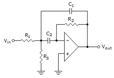
a) A0 = R2R1
b) A0 = R1R2
c) A0 = R22R1
d) A0 = R12R2
Answer: c
Explanation: The total output C = CINPUT + COUTPUT that is the gain capacitor.
∴ The total Resistance is equal to the Resistance input and Resistance output.
Again, the total resistance gain = R1R2R1+R2
Hence, the gain = A0 = R22R1.
2. Two network functions are given below.
H1 = 1s2+2√s+1, H2 = 1s3+2s2+2s+1
The frequency response indicates that the filter is ___________
a) Low-pass
b) Band-pass
c) High-pass
d) Band reject
Answer: a
Explanation: | H1 |2 = 1[(jω)2+2√jω+1][(jω)2+2√jω+1]
Similarly, | H2 |2 = 11+ω6
Therefore at ω = 0, 1 and ∞, we have | H |2 = 1, 12 and 0 respectively.
Hence, the filter is a Low-pass filter.
3. A particular band-pass function has a network function as H(s) = 3ss2+4s+3 then, its quality factor Q is ___________
a) 34
b) 23√
c) 3√2
d) 3√4
Answer: d
Explanation: H(s) = Kss2+as+b
Then, quality factor is given as b√a
Here, b = 3, a = 4
∴ Q = 3√4.
4. In which of the filter circuits given below, will the bandwidth be equal to the critical frequency?
a) Low-pass
b) High-pass
c) Band-pass
d) Band-stop
Answer: a
Explanation: Bandwidth can be calculated by considering,
Largest positive value – Smallest Positive Value
Here, in case of the Low-pass filter only, the largest positive value will of course be the critical frequency, beyond which frequencies have to be blocked. Hence, the bandwidth in a Low-pass filter equals the critical frequency.
5. In the circuit given below, the Roll-off of the filter is _______________
a) 20 dB/decade
b) 40 dB/decade
c) 60 dB/decade
d) 80 dB/decade
Answer: a
Explanation: The given filter is a first order Band Pass Filter.
Also, the Roll-off of the filter is depends upon the order of the filter.
For a first order it is 20dB/decade, for second order it is 40dB/decade, and so on.
Therefore, the Roll-off of the filter = 20 dB/decade.
6. The circuit given below, represents which filter?
a) Low-pass
b) High-pass
c) Band-pass
d) Band-stop
Answer: b
Explanation: From the given circuit, we can infer that Roll off of the Filter circuit is 80dB/decade. This Roll-off value is obtained as second order high pass filter followed by another 2nd order HPF results in an HPF.
Therefore the circuit represents a High-pass Filter.
7. A Low-pass filter circuit has a cut-off frequency of 1.23 kHz. The bandwidth of the filter is ______________
a) 2.46 kHz
b) 1.23 kHz
c) 0.615 kHz
d) 3.69 kHz
Answer: b
Explanation: The bandwidth is defined as the highest cut-off frequency to the lowest cut-off frequency. Here the lowest cut-off frequency is Zero.
For a Low-pass filter therefore, Cut-off Frequency = Bandwidth of the filter
∴ Bandwidth = 1.23 kHz.
8. For the circuit given below, the Roll-off value of the filter is _____________
a) 20 dB/decade
b) 40 dB/decade
c) 60 dB/decade
d) 80 dB/decade
Answer: d
Explanation: The given filter is a first order Band Pass Filter. Also, the Roll-off of the filter is depends upon the order of the filter. For a first order it is 20dB/decade, for second order it is 40dB/decade, and so on.
Therefore, the Roll-off of the filter = 20 dB/decade.
Roll of first order low pass Butterworth filter is 20dB/decade.
Now here two stages of second order Low-pass Butterworth filter are cascaded
∴ Roll-off = 20*4 = 80 dB/decade.
9. For providing a Roll-off greater than 20dB/decade/pole, filters with which characteristics are useful?
a) Butterworth
b) Chebyshev
c) Bessel
d) Butterworth & Bessel
Answer: b
Explanation: Roll off is a term commonly refers to the steepness of the transmission function wrt to the frequency.
For a Chebyshev filter, the Roll-off value greater than 20. This characteristic feature is useful when a rapid roll-off is required because it provides a Roll-off rate of more than 20.
On the other hand, both Butterworth and Bessel have the Roll-off rate less than or equal to 20 dB/decade/pole.
10. In a moving iron meter, the deflection torque is proportional to?
a) Square of the current through the coil
b) Current through the coil
c) Sine of measurand
d) The Square root of the measurand
Answer: a
Explanation: We know that Td = 12I2dldθ
Hence, the deflection torque is proportional to the square of the current through the coil.
11. The filter which passes all frequencies above fc by attenuating significantly, all frequencies below fc is _______________
a) Low-pass
b) High-pass
c) Band-pass
d) Band-stop
Answer: b
Explanation: A high-pass filter is one which passes all frequencies above fc by attenuating significantly, all frequencies below fc.
12. The circuit given below represents which type of filter circuit?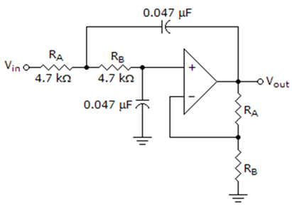
a) Low-pass Filter
b) High-pass Filter
c) Band-pass Filter
d) Band-stop Filter
Answer: c
Explanation: The given circuit is a first order Band Pass Filter. Also, the Roll-off of the filter depends upon the order of the filter. For a first order it is 20dB/decade, for second order it is 40dB/decade, and so on.
13. For the circuit given below, the cut-off frequency of the filter is ________________
a) 3225.8 Hz
b) 7226 Hz
c) 3225.8 kHz
d) 7226 kHz
Answer: c
Explanation: We know that, F = 12π×(R1×R2)×(C1×C2)
Where, R1 = 4700 Ω, R2 = 4700 Ω, C1 = 0.047 × 10⁻⁶ F, C2 = 0.047×10⁻⁶ F
∴ F = 12π×(4700×4700)×(C1×C2)
= 12π×48796.81×10−12
= 1062π×0.04879681
= 1060.30654156042 = 3225.8 kHz.
14. The circuit given below represents which type of filter circuit?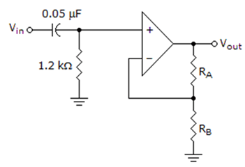
a) Low-pass Filter
b) High-pass Filter
c) Band-pass Filter
d) Band-stop Filter
Answer: b
Explanation: We know that the position of Resistance (R) and Capacitance (C) determines whether it is Low-pass Filter or High-Pass Filter. If R is connected directly to source and the capacitor connected in parallel to it, then it is a Low-pass Filter and if the position of R and C are inter change then high pass filter is formed.
Here since R and C are in series and also R is not connected directly to the power source, hence the filter is a High-pass Filter.
15. For the circuit given below, the cut-off frequency of the filter is ________________
a) 5283 kHz
b) 5283 Hz
c) 2653.1 kHz
d) 2653.1 Hz
Answer: d
Explanation: We know that, F = 12π×R×C
Where, R = 1200 Ω, C1 = 0.05×10⁻⁶ F
∴ F = 12π×1200×C
= 12π×60×10−6
= 1062π×60 = 2653.1 Hz.
Advanced Problems on Filters – 2
1. In a parallel RL circuit, 10 A current enters into the resistor R and 15 A current enters into the Inductor L. The total current I is _____________
a) 15.5 A
b) 25.05 A
c) 18.03 A
d) 30.15 A
Answer: c
Explanation: Currents in resistance and inductance are out of phase by 90°.
Hence, I = I21+I22
Or, I = [102 + 152]0.5
Or, I = 100+225−−−−−−−−√=325−−−√
= 18.03 A.
2. In the circuit given below, a dc circuit fed by a current source. With respect to terminals AB, Thevenin’s voltage and Thevenin’s resistance are ____________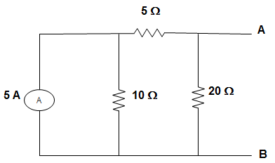
a) VTH = 5 V, RTH = 0.75 Ω
b) VTH = 7.14 V, RTH = 2.14 Ω
c) VTH = 7.5 V, RTH = 2.5 Ω
d) VTH = 5 V, RTH = 1 Ω
Answer: b
Explanation: VTH = 5X1035 X 5 = 7.14 V
Also, RTH = 5X1535 = 2.14 Ω.
3. In the circuit given below, the value of R is ____________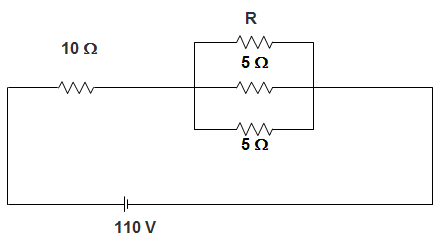
a) 12 Ω
b) 6 Ω
c) 3 Ω
d) 1.5 Ω
Answer: b
Explanation: The resistance of parallel combination is given by,
Req = 403 – 10 = 3.33 Ω
Or, 13.33=112+115+115
Or, R = 6 Ω.
4. In the circuit given below, M = 1. The resonant frequency is _______________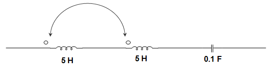
a) 145.3 Hz
b) 0.1453 Hz
c) 1.453 Hz
d) 14.53 Hz
Answer: d
Explanation: IEQ = L1 + L2 + 2M
LEQ = 5 + 5 + 2 × 1
= 10 + 2 = 12 H
∴ FO = 12πLC√
= 12π12×0.1√
= 0.1453 Hz.
5. A thermistor is used for ____________
a) Over voltage protection
b) Temperature alarm circuit
c) Automatic light control
d) Automatic sensor
Answer: b
Explanation: The resistance of a thermistor decreases with increases in temperature. It is used to monitor the hot spot temperature of electric machines.
6. Two network functions are given below.
H1 = 1s2+2s+1, H2 = 1s3+3s2+3s+1
The frequency response indicates that the filter is ___________
a) Low-pass
b) Band-pass
c) High-pass
d) Band reject
Answer: a
Explanation: | H1 |2 = 1[(jω)2+2jω+1][(jω)2+2jω+1]
Similarly, | H2 |2 = 11+ω6
Therefore at ω = 0, 1 and ∞, we have | H |2 = 1, 12 and 0 respectively.
Hence, the filter is a Low-pass filter.
7. A particular band-pass function has a network function as H(s) = ss2+2s+1 then, its quality factor Q is ___________
a) 34
b) 12
c) 32
d) 14
Answer: d
Explanation: H(s) = Kss2+as+b
Then, quality factor is given as b√a
Here, b = 1, a = 2, K = 1
∴ Q = 12 = 0.5.
8. The filter which passes all frequencies above fc by attenuating significantly, all frequencies above fc is _______________
a) Low-pass
b) High-pass
c) Band-pass
d) Band-stop
Answer: b
Explanation: A high-pass filter is one which passes all frequencies above fc by attenuating significantly, all frequencies below fc.
9. For a Band Pass Filter, the slope of the filter is given as 80dB/decade. The order of the Band Pass Filter is __________
a) 10
b) 8
c) 4
d) 6
Answer: b
Explanation: The Bode plot is a logarithmic plot which helps in fitting a large scale of values into a small scale by the application of logarithm. Plotting the slope 80dB/decade on the Bode plot, we get n=8. Hence the order of the Band Pass Filter is 8.
10. In which of the filter circuits given below, will the bandwidth be equal to the critical frequency?
a) Low-pass
b) High-pass
c) Band-pass
d) Band-stop
Answer: a
Explanation: Bandwidth can be calculated by considering,
Largest positive value – Smallest Positive Value
Here, in case of the Low-pass filter only, the largest positive value will of course be the critical frequency, beyond which frequencies have to be blocked. Hence, the bandwidth in a Low-pass filter equals the critical frequency.
11. For providing a Roll-off greater than 60dB/decade/pole, filters with which characteristics are useful?
a) Butterworth
b) Chebyshev
c) Bessel
d) Butterworth & Bessel
Answer: b
Explanation: Roll off is a term commonly refers to the steepness of the transmission function with respect to the frequency. For a Chebyshev filter, the Roll-off value greater than 60. This characteristic feature is useful when a rapid roll-off is required because it provides a Roll-off rate more than 60. On the other hand, both Butterworth and Bessel have the Roll-off rate less than or equal to 60 dB/decade/pole.
12. A Low-pass filter circuit has a cut-off frequency of 50 kHz. The bandwidth of the filter is ______________
a) 24.6 kHz
b) 50 kHz
c) 61.5 kHz
d) 36.9 kHz
Answer: b
Explanation: The bandwidth is defined as the highest cut-off frequency to the lowest cut-off frequency. Here the lowest cut-off frequency is Zero.
For a Low-pass filter therefore, Cut-off Frequency = Bandwidth of the filter
∴ Bandwidth = 50 kHz.
13. Given a system function H(s) = 1s+10. Let us consider a signal sin 10t. Then the steady state response is ___________
a) 1
b) 2
c) 0
d) 5
Answer: c
Explanation: H(s) = V(s)J(s)
= 1s+10
V(s) = 1s+10 . J(s)
J(s) = L (sin 10t) = 10s2+100
V (s) = 1s2+100.10s+10
VSS = lims→0 sV(s)
= 0.
14. Current I = – 1 + 2–√ (sin (ωt + 60°)) A is passed through three meters. The respective readings will be?
a) 2–√ A, 2–√ A and 1 A
b) 1 A, 2–√ A and 1 A
c) – 1 A, 2–√ A and 2–√ A
d) -1 A, 1 A and 1 A
Answer: c
Explanation: We know that a PMMC instrument reads only DC value and since it is a centre zero type, so it will give – 1.
So, rms = 12+(2√2√)2−−−−−−−−−√=2–√ A
Moving iron also reads rms value, so its reading will also be 2–√ A.
15. For a Band Pass Filter, the slope of the filter is given as 40dB/decade. The order of the Band Pass Filter is __________
a) 2
b) 3
c) 4
d) 6
Answer: c
Explanation: The Bode plot is a logarithmic plot which helps in fitting a large scale of values into a small scale by the application of logarithm. Plotting the slope 40dB/decade on the Bode plot, we get n=4. Hence order of the Band Pass Filter is 4.